FUmanoids Humanoid League - KidSize Team Description Paper 2011
Daniel Seifert, Hamid Reza Moballegh, Steen Heinrich, Stefan Otte, Sebastian Mielke, Naja von Schmude, Thomas Weiÿgerber, Kenneth Würfel, Rico Jonschkowski, Johannes Kulick, Moritz Fröhlich, Jan Streckenbach, George Lubitz, Nico von Geyso, Michael Schubert, Fu Yao, Steen Puhlmann, Oscar Salvador Morillo Victoria, Lutz Freitag, Prof. Raúl Rojas
Institut für Informatik, Arbeitsgruppe Künstliche Intelligenz, Freie Universität Berlin, Arnimallee 7, 14195 Berlin, Germany
Abstract This document gives an overview of the current hard- and software of the FUmanoids team of humanoid robots. Initially these were developed for RoboCup 2009 in Graz and participated again in RoboCup 2010 in Singapore. For the upcoming RoboCup competitions in 2011, an improved system is developed based on the achieved results of the last years. The mechanical structure of the robot is a self made construction with a total height of 59cm, including 21 actuated degrees of freedom based on Dynamixel RX28 and RX64 servos. Central processing, including machine vision, planning and control is performed using an ARM based platform. Behavioral algorithms are implemented using the Extensible Agent Behavior Specication Language (XABSL). This paper explains the software and hardware used for the robot as well as control and stabilization methods developed by our team.
1 Introduction
Humanoid robots have many potential applications, which make this area very attractive for researchers. However, many of the yet developed humanoids suer from over-designed and too complicated hardware and software which is still far from the human model. The FUmanoid project was started in 2006 in the Arti cial Intelligence group at Freie Universität Berlin, which had had a successful history in RoboCup for many years with the FU-Fighters team. In its rst year it has shown an excellent performance by winning the 3rd place in the humanoid league in kidsize class, presenting the lightest and the least expensive football playing robots in its class. This result was surpassed in 2009 and 2010 by winning second place with a new hard- and software design. This was achieved by improving several solutions, which will be explained briey in this paper. The FUmanoid project is a step towards research and development of robots which oer more real human-interaction, can perform tasks in our environment and will be able to play an important role in our daily life.
2 Hardware Design
(This section contains subsections; see below.)
2.1 Mechanical Structure
The actuators used in the FUmanoid robots are from the Dynamixel servomotor family produced by Robotis Inc. Korea. The motion mechanism consists of 21 degrees of freedom distributed in 7 per leg, 3 per arm and one degree of freedom moving the head horizontal.
Knee joints were considered to bend in both directions for 2009 competitions, which help faster response of the robot in backward walking. However, this property can be limited via software. Eorts have been made to hold the proportions as human-like as possible. Table 1 illustrates the physical measurements of the robot. To facilitate exchange of the players, all robots use mechanically the same structure.
Table 1. Physical measurements of the robot
| Quantity | Value | Unit |
|---|---|---|
| Overall Height 60 | cm | |
| COM Height | 45 | cm |
| Weight | 4320 | G |
| Leg Length | 33 | cm |
| Foot Area | 120 | cm2 |
| Arm Length | 25 | cm |
| Head Length | 10 | cm |
2.2 Actuators
The actuators used in the FUmanoid robots are Dynamixel AX-28 and Dynamixel RX-64 servomotors, produced by Robotis Inc. Each actuator has its own microcontroller which implements adjustable position control. It also calculates many other parameters such as rotation speed and motor load which can be accessed through a single-bus, high-speed serial communication protocol. This facilitates the construction of an extendable network of motors which can be individually accessed and controlled by a single microprocessor. The parameters of the actuators used in FUmanoid robots are summarized in table 2.
Table 2. Characteristics of the servomotors used
| | | | Weight g | Gear Ratio | Max Torque kgf.cm | Speed sec/60o | Resolution degrees | |-------|-----|---------|----------|--------|---------|---------| | AX-64 | 125 | 1 : 200 | 64.4(@15V) | | 0.188 | 0.35 | | RX-28 | 72 | 1 : 193 | 28.3(@12V) | | 0.167 | 0.35 |
2.3 Sensors
Due to the single bus structure, almost every type of sensor can be easily integrated with the hardware. The robot is equipped with the following sensors:
Actuator feedback: The feedback of the actuators includes the current joint angle, the current motor speed, and the load. Because all of these values are derived from the only feedback sensor of the actuators (the position potentiometer), the latter two values are less reliable. There are also other measured values which can be accessed through the Dynamixel serial interface, such as supplied voltage and temperature, which can be used for safety purposes. Joint position measurement is very helpful in stable gait generation for the robots.
Ground contact sensors: Ground contact sensors are used to synchronize the walking with the mechanical properties of the robot.
IMU sensor: An IMU is used in the robots for two purposes, rst to help stabilization of walking and second to calculate camera perspective in order to obtain localization data.
Visual feedback: The robot is equipped with one camera [4] which can cover a full range of 180 x 90 degrees.
Each hardware unit has a unique ID for packet identication. A broadcasting ID can be used to send the same data packet to all existing units on the bus.
2.4 Processors and communications
Each robot is equipped with two computation units.
The main computational unit is an IGEPv2 board featuring the DM3730 processor running at 1 GHz. This CPU is from the ARM Cortex A8 family and includes a DSP that can be used for additional computing. The IGEPv2 motherboard has several interesting features which make it ideal as a brain for humanoid robots. These include low weight and power consumption, direct camera connection and easy extension for a variety of devices. The board also supports Wireless LAN which is used for team communication.
For communication with the hardware units, namely motors and sensors, a microcontroller is used that serves as a preprocessing and optionally stand-alone motor control unit. Data can be requested from the main unit and actions, e.g. movements of the robot, triggered via a dedicated serial connection.
3 Software Design
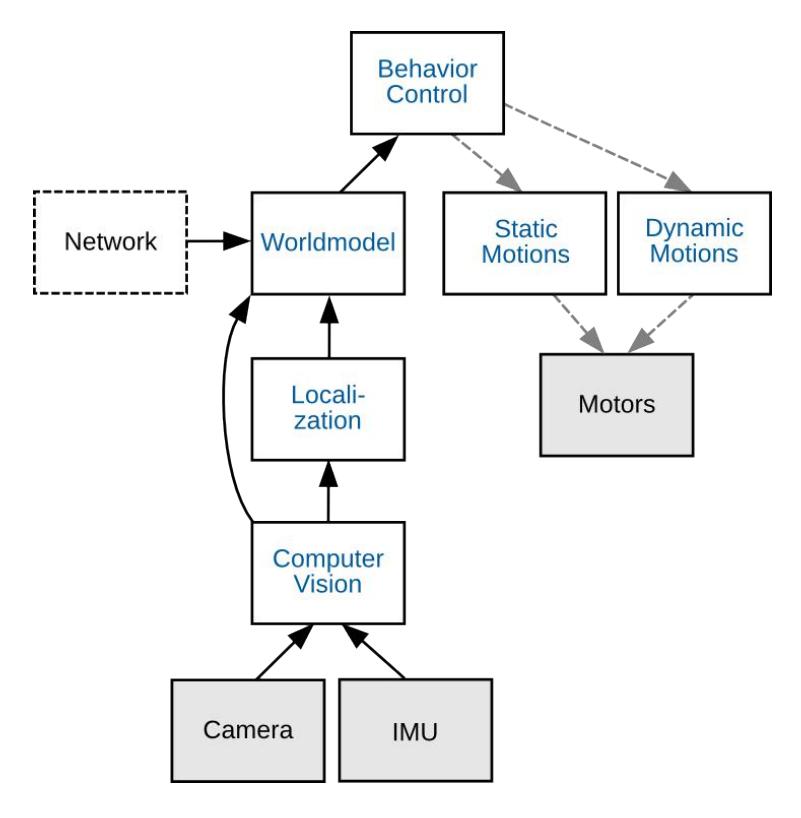
Fig. 1 shows the block diagram of the software which runs on the robot. The main blocks of the program are:
Hardware Interface: The Hardware interface contains all low level routines to access hardware of the robot including sensors and actuators.
4 Stabilization and Control
Stabilizing humanoid robots is a challenging subject which has attracted many researchers who have developed widely varying techniques. These techniques range from static COM methods to dynamic nonlinear control methods using multi-DOF of under-actuated inverted pendulum models. A dierent approach was developed for the biped walking stability problem by McGeer, who pioneered the idea of passive dynamic walking [6]. This approach which is both simple and direct has been followed by Collins, Wisse and Ruina and has been improved with dierent techniques to obtain remarkable 3D walking stability and speed [3].
Both 2D and 3D passive dynamic walkers receive their energy from changes in height of their COM as they walk down a shallow heel. Therefore the original passive walking is not suited to applications such as football playing in which the robot should not only walk on a level surface but also change its velocity and direction very often. To solve this problem, further research has presented several methods of pumping energy into a passive walker such as torso control [5], active toes [2] and virtual gravity [1].
The aim of our biped walking research is to develop a walking technique which uses very limited sensory data (i.e. only joint angle and phase reset of the step) and provides stability over a wide range of velocities. To examine the present solutions and to be also able to study new ideas, a simplied model of the robot has been simulated with ODE1 and its walking stability has been tested in simulations. Using this simulator, some new techniques have been introduced to improve walking stability and to control the walker.
However implementing the simulated control ideas in a real robot is as di cult as re-doing the whole work despite of the simulated results. This is because of the vast dierence between the simulated and the real platform. Actuators used in most of the humanoid platforms are servomotors, which have normally a high grade of damping regarding the gear reduction ratio and have also strong limits in their maximum speed and/or applied torque. This is very disadvantageous as the energy of the COM is of great importance in passive dynamic walking. A direct torque control is also provided by almost none of the commercially available servomotors.
As a test, the friction of the ankle actuators of each foot was reduced by removing a gear from each, turning the ankles into low friction joints using only the position as sensory data. The data derived from these sensors are then used in the control program which nds the stance foot at each step and controls all active actuators regarding to the stance angle.
To have the passive walking controlled and supplied from the robot's own energy, one should be able to either switch the actuators to act as passive free running and active in dierent walking phases or to decrease the stiness of the servos and use them in a mixed way both as sensors and actuators. Using the later technique, stable walking at velocities up to 40cm/s has been achieved.
Furthermore a kinematic module with complete forward and inverse kinematic was introduced in 2010. The forward kinematic (based on the Denavit-Hartenberg convention) is used to improve the odometry of the robot and the pose determination for the camera which improves the self localization of the robot. The inverse kinematic allows to dene motions like walking or kicking in an easier way. Also it is more precise than the method used in earlier versions of the robot.
References
- F. Asano, M. Yamakita: Virtual Gravity and Coupling Control for Robotic Gait Synthesis. In: IEEE Trans. on Systems, Man and Cybernetics, Part A: Systems and Humans, Vol. 31, No. 6, pp. 737-745, November 2001.
- S. Behnke, J. Müller, M. Schreiber: Toni: A Soccer Playing Humanoid Robot. In: RoboCup 2005: 59-704.
- S. H. Collins, M. Wisse, A. Ruina: A Three-Dimensional Passive-Dynamic Walking Robot with Two Legs and Knees, Collins, In: International Journal of Robotics Research, Vol. 20, No. 2, Pages 607-615, 2001
- B. Fischer, H. Moballegh, R. Rojas: Low Cost Synchronized Stereo Aquisition System for Single Port Camera Controllers; 2010 IEEE/RSJ International Conference on Intelligent Robots and Systems, October 18-22, 2010, Taipei International Convention Center, Taipei, Taiwan
- M. Haruna, M. Ogino, K. Hosoda, A. Minour: Yet another humanoid walking Passive dynamic walking with torso under a simple control In: Int. Conference on intelligent robots and system, 2001
- T: McGeer: Passive dynamic walking. In: International Journal of Robotics Research 9(2):62-82. 1990.
- H. Moballegh, M. Mohajer, R. Rojas: Increasing foot clearance in biped walking: Independence of body vibration amplitude from foot clearance. In: L. Iocchi, H. Matsubara, A. Weitzenfeld, C. Zhou, editors, RoboCup 2008: Robot Soccer World Cup XII, LNCS. Springer, 2008.