SigmaBan Team Description Paper Humanoid KidSize League, Robocup 2011
H. Gimbert, L. Gondry, O. Ly, Ph. Narbel
CNRS, INRIA Flowers, LaBRI, University of Bordeaux 1 33405 Talence, FRANCE
Abstract This paper gives a short overview of the design of a kid-size humanoid robot able to play soccer in an autonomous way. It describes the main hardware and software components of the robot in their current states.
(Les robots ne sont pas toujours ceux que l'on croit ou ceux qu'ils croient ˆetre.)
Introduction
SigmaBan is an on-going robotic project whose team members are researchers at Bordeaux 1 University and INRIA's Flowers [6]. This project stems from the desire to better understand the problems arising from building a fully autonomous bipede capable of human-like motions, and to thoroughly study their solutions from an empirical and a theoretical point-of-view. In this context, several prototypes have been already built and tested [3,4,1], focussing on walking, locomotion, interactions, and proposing some new solutions in terms of robot mechanical structure (e.g. spine-oriented) and compliance. The idea of playing a dynamic game like soccer – a very interesting testbed for producing complex situations in a constrained environment – has driven the team to design a new robot with an improved structure, including video/image analysis and planning behaviour tactics, a necessary step forward to make the robot gain autonomy. This short paper gives an overview of this robot system in its current state, for the prospect of making it participate to Robocup 2011.
Mechanical Structure
The mechanical structure of the robot involves 22 degrees of freedom: 6 for each leg, 2 for the pelvis (rotation in the sagittal plane and in the coronal plane), 3 for each arm, and 2 for the head (pitch and yaw rotations). The global shape of the robot is globally standard. However, as we already pointed out, our design focuses on the compliance of the structure. Our goal has been indeed to improve the intrinsic stability of the system, and to avoid as much as possible inelastic shocks. Accordingly, we included several springs to the structure, as well as some flexible and soft materials like plastics and foam. We also introduced free linear joints controlled by dampers only. These joints absorb vertical shocks occuring during the gait, especially at the landing of the foot on the ground. These joints are located in the following places of the mechanical structure:
- In the hips, allowing a vertical linear motion.
- In the spine, allowing a vertical motion as well.
- In the shoulders, making the rotation of shoulder in the coronal plane compliant.
These joints introduce new not-controlled degrees of freedom, making the robot semi-passive. Moreover, the dampers are also used in another way, that is, as feedback force sensors. For instance, the vertical damper located in the hip directly samples the ground reaction force. This force can thus be computed from the measure of the length of the damper by taking into account its friction and spring coefficients. Even if more complex control is involved, the empirical experiments have showed very good stability properties, and new possibilities for improving the robot motions in the future.
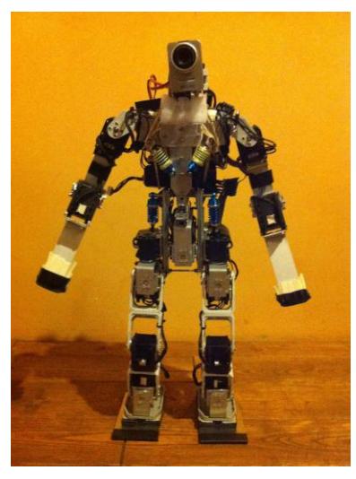
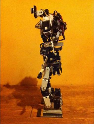
| Value | Unit | |
|---|---|---|
| Degrees of freedom | 22 | |
| Weight | 3.7 | kg |
| Height | 58 | cm |
| Leg Length | 27 | cm |
| Arm Length | 27 | cm |
| Foot Length | 13 | cm |
Actuators and Sensors
All the joints are actuated by servomotors. We use off-the-shelf servomotors, that is, Dynamixel RX-28, Dynamixel RX-64, and Standard RC servomotors for the head motion. We also use dynamixel servo position control (and feedback) in a standard way, but we exploit their maximum-torque control in order to again introduce compliance in the motions of the robot. Besides, we use standard servomotors for the head because of their lighter weight, and also because strict position control without feedback is sufficient for the head.
The robot gets feedbacks through the following main sensors:
- Gyroscopic sensor. We use a 2-axis gyroscopic sensor measuring the rotation speed in the coronal and the sagittal planes. This sensor is located on the hip. The component we use is an IDG500.
- Accelerometer. We use a 3-axis accelerometer sensor measuring the acceleration applied to the robot structure mixed with the gravity force. This sensor is more difficult to interpret, however it gives an absolute position information which completes in a useful way the measures of the gyroscopic sensor. The component we use here is an ADXL335.
- Camera. At the moment, the head of the robot is equiped with a Philips webcam of type SPC620NC. It samples pictures with a low resolution (160x120 pixels) with a frequency of 8 Hz.
- Joint Positions. On top of that, the robot uses also joint position feedback provided by each dynamixel servo. In particular, considering some particular motion phases, one decreases the torque of some servo to make the motion compliant. Therefore, at these points, the joint position feedback becomes essential.
Processing Units
The embedded system consists of two main processing units: an ARM7 microcontroller without operating system, and an ARM9 microcontroller equiped with Linux. The ARM9 has 64MB SDRAM and its frequency is 210MHz, and the ARM7 has 64kB RAM with 55 MIPS. More precisely:
The ARM9 microcontroller is in charge of the high-level behaviour management and the execution of the high-level programmed components:
- High-level decision processes. The behaviour of the robot is driven by state machines, mostly statecharts and finite state-machines (FSM).
- High-level motor primitive parametrization. The different movement of the robot are defined in terms of motor primitives. These motor primitives have high-level parameters used to adapt them in a continuous manner. These are the parameters through which the high-level system drives the robot.
- Complex feedback analysis.
- Vision module.
- Communication with external entities (via WiFi IP protocol)
The ARM7 microcontroller is in charge of the low-level management:
- Motion scheduling. Part of motions are defined by mean of splines. These splines are generated at low level in order to ensure real-time (50 Hz).
- Elementary control unit. On top of splines, the motions are defined with several PID controller acting on different part of the robot, and also on some parameters of the motion (e.g., spline amplitude).
- Servomotor control. The processing unit communicates with dynamixel servos via a RS-485 bus. It sends orders to standard RC servo via PWM signal generation.
Both processing unit communicate via a serial USART bus. We now describe in more details some of the above components, in particular the vision module and the motion control system.
Vision Module
The vision module of the SigmaBan robot is responsible for making all the necessary image processing and analysis. This module runs on the Linux of the ARM9 system, and it consists of a collection of programs and components written in C and C++. Most of their implemented algorithms use the OpenCV 2 library (Open Source Computer Vision Library) [5,2]. This large computer vision library allowed us to experiment and tune many different tactics for detecting and tracking objects of interest like the ball, the goal posts, the other players, and the line fields. The vision module currently has the following characteristics:
- It essentially uses color images with the HSV color space.
- For detecting and tracking objects, the vision module essentially use various smoothing operators and image morphological transformations, hierarchical contour detection algorithms, Hough transforms, circle/ellipse/polygon fitting, and histogram analysis.
- Robustness of the detection/tracking processes has also been taken care of, in particular with respect to object obstructions, by using explicit hypothesis upon the properties of the objects, and with respect to lighting and color variations, by using histogram transformations and distances.
- Self-localization and estimation of object relative positions are still elementary, as they only rely on sizes of the detected objects, and on the angles of the robot's head.
The video/image analysis algorithms of the vision module are designed and tested for different image resolutions (640x480, 320x240, 160x120). Indeed, even if the resolution currently on use is 160x120 (see Sec. 2.2), we are looking forward to include more computing power, and also to exploit opportunistic resolutions, so as to be able to associate them to the states of the robot. Also, in order to pre-test some of the algorithms of the vision module, we design dynamic models of soccer field and robots in the Second Life virtual world. This allowed us for instance to more easily obtain well-defined complex sequences of images, sets of characteristic obstruction situations, and strict uniform ligthing conditions.
Behaviour Control
The motor behaviour of the robot is driven by two layers. The high-level behaviour is defined in terms of state machines. In turn, this state machines control low-level motor primitives. States define global behaviour, e.g. , "Searching the ball", "Tracking the ball", "Adjusting position for shooting", etc. There are two main state machines: One of them defines the behaviours of the head which is in charge of searching and tracking the ball. The second one defines the locomotion strategy. The state machines control motor primitives: they launch and stop them and they drive them via reduce sets of user-defined parameters.
Motion Design and Control
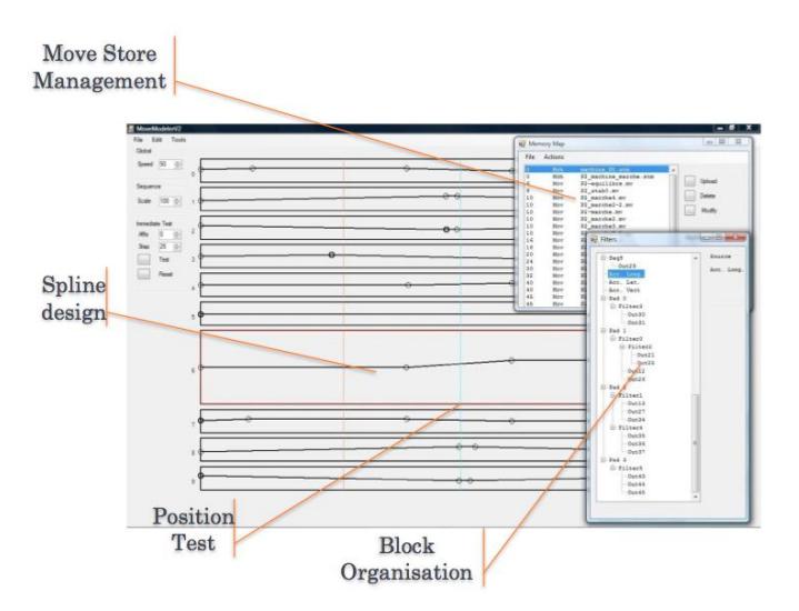
We design motions through a graphical framework environment we have developed where motions are subdivided into modules called parameterized motor primitives. Here is the general aspect of this environment:
Sagittal Stabilization
In the sagittal plane, we use each motor primitives described above enforced by PID controllers whose gain are adjusted by expert knowledge and experiments. We also use compliance in the sagittal rotation of the lower joint of the vertebral column, enforced in a spring mode. Error is re-injected in the sagittal rotation of the shoulder and in the pelvis sagittal horizontal position via a PID controller.
Gait Control
At the moment, we designed two different dynamic gaits: The first one is a slow one (0.85 Hz). A characteristic of this gait is that the grounded leg is straight and the other is compliant. This gait is used for precise locomotion, for instance the adjustment of the position for shooting the ball. The second gait is faster (1.35 Hz), as it is dedicated to move around in the game field. Note that the design of the gaits is still a work in progress, as we are searching for optimal uses of the semi-passive mechanical structure of the robot (see Sec. 2.1).
References
- Rhoban Project. 2009. http://www.youtube.com/user/theRhoBan.
- G. Bradsky and A. Kaehler. Learning OpenCV: Computer Vision with the OpenCV Library. O'Reilly, 2008.
- O. Ly and P.-Y. Oudeyer. Acroban the humanoid: Compliance for stabilization and human interaction. In IEEE/RSJ International Conference on Intelligent Robots and Systems, 2010.
- O. Ly and P.-Y. Oudeyer. Acroban the humanoid: Playful and compliant physical child-robot interaction. In ACM SIGGRAPH'2010 Emerging Technologies, Los Angeles, 2010.
- OpenCV Home Page. http://opencv.willowgarage.com/wiki/ (accessed, January 2011).
- Flowers Team. http://flowers.inria.fr.