YRA Team Description 2011
Mohammad HosseinKargar, MeisamBakhshi, Ali Esmaeilpour, Mohammad Amini, Mohammad Dashti Rahmat Abadi, Abolfazl Golaftab, Ghazanfar Zahedi, Mohammadreza Jenabzadeh
Yazd Robotic Association; Islamic AZAD University YAZD Branch; Safaeieh, YAZD, IRAN
Abstract This document describes hardware and software of the robots developed by the "YRA" Team for the RoboCup soccer kid -size competitions to be held in Turkey 2011 .The system we developed has some features .They are high mobility, strong kicks, well-designed control system, position estimation by one camera and user-friendly interface .The robot has 20 actuated degrees of freedom based on Dynamixel AX12 servos .Central Processing, including Machine vision, Planning and control is performed using a Roboard-110 which is an ARM based 1000MHz platform .This paper explains the software and hardware used for the robot as well as control and stabilization methods developed by our team.
1. Introduction
Humanoid robots have many potential applications, which make this area very attractive for researchers .However many of the yet developed humanoids suffer from over-designed and too complicated hardware and software which is still far from the human model.
The Humanoid team was started in 2009 in the Yazd Robotic Association at Azad University of Yazd, which has had a successful and long history in RoboCup with the YRA rescue and deminerteams. This is the Second experiment of YRA in RoboCup soccer at kid-size class after IRANOPEN 2010 . so we try to show new performance and solutions, that we describe some of them in this paper.
2.1 Mechanical Structure
The actuators used in the YRA robots is the Dynamixel servo motor family produced by RobotisInc . Korea .The motion mechanism consists of 19 degrees of freedom distributed in 6 per leg, 3 per arm and other one degrees of freedom as a pan-tilt system holding the head.
Fig.1 shows one of the constructions used for the motion mechanism of the robots.
Mechanical Structure of YRA robots started with Bioloid robot kit produced by RobotisInc .but now we are working on a new and optimized structure of Humanoid robots to participate in Robocup competitions.
Table1 illustrates the physical measurements of the robot .To facilitate exchange of the players, all robots use mechanically the same structure.
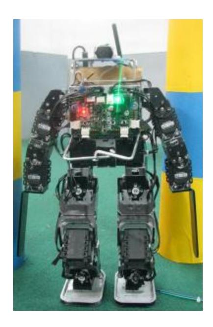
Table 1. Physical measurements of the robot
| Quantity | Value | Unit |
|---|---|---|
| Overall Height | 48 | Cm |
| Weight | 2350 | G |
| Leg Length | 24 | Cm |
| Foot Area | 60 | cm2 |
| Arm Length | 19 | Cm |
| Head Length | 12 | Cm |
2.2 Actuators
The actuators used in YRA robots are "Dynamixel AX-12" servomotors, produced by Robotis Inc . Each actuator has its own microcontroller which implements adjustable position control using potentiometer position feedback .It also calculates many other parameters such as rotation speed and motor load which can be accessed through a single-bus, high-speed serial communication protocol . This facilitates the construction of an extendable network of motors which can be individually accessed and controlled by a single microprocessor.
The parameters of the actuators used in YRA robots are summarized in table 2.
Table 2. Characteristics of the servomotors used in YRA Robots
| Actuator | Weight (g) | Gear Ratio | Max Torque kgf.cm | Sec/60degree | Resolution degrees |
|---|---|---|---|---|---|
| Dynamixel AX-12 | 55 | 1 : 254 | 16.5 (at 10v) | 0.196 | 0.35 |
2.3 Processors and communications
Each Robot has an embedded Roboard RB-110 (Fig .2) produced by Roboard.com. this board make our Robots more active and intelligent. It is a complete computer system based on the Vortex86DX CPU, a 32bit x86 CPU running at 1000MHz with 256MB RAM. This board allows us to install a Windows Xp Operating System onto a bootable Micro-SD card. The RoHS compliant CPU
board measures just 96mm x 50mm and accepts a voltage input range from 6V-24V DC whilst providing extremely low power consumption.
RoBoard has the rich I/O interfaces to the servo, DC motors, sensors, gyroscope, accelerometers and other devices. Also, it has build-in the PWM 16 Ch, Hi-Speed serial, TTL serial, RS-485,USB V2.0 x 3, A/D convert, I2C bus, 10/100M LAN and Mini PCI socket.
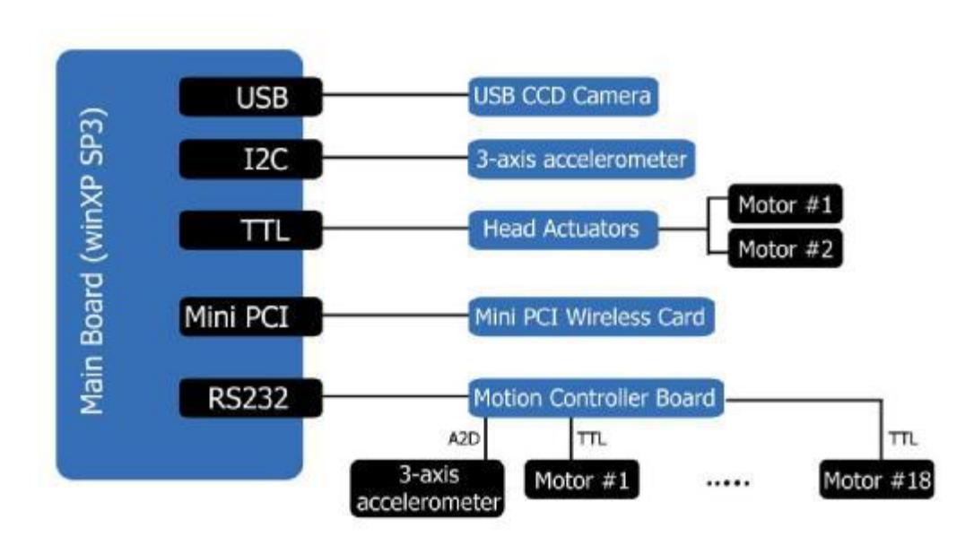
Most of hardware units such as motions controller board and Camera are connected to the main processor via an RS232 and USB bus. The communication solution for other devices are shown in system diagram.
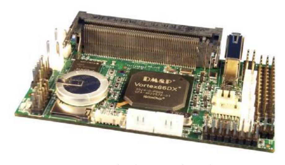
Table 3. Main Board Specifications
| RB-110 Specifications | ||
|---|---|---|
| CPU | DM&P Vortex86DX-1000MHz | |
| BIOS | AMI BIOS | |
| Memory | 256MB DDR2 onboard | |
| ADCs | Analog Devices AD-7918 10-bit | |
| Hi-Speed UART | FTDI FT2232HL Hi-Speed UART | |
| I/O Interface | Micro SD slot x1 | |
| USB port x 1 (USB 2.0 version) | ||
| 2.54mm 3-pin box header for PWM x 16 | ||
| 2.54 mm 10-pin box header for RS-232 x 1 | ||
| 2.54 mm 10 pin box header for Hi-speed (COM 6) x 1 | ||
| 2.0 mm 4 pin header for High speed (COM 5) x 1 | ||
| 2.0 mm 4-pin header for RS-485 x 1 | ||
| 2.0 mm 4-pin header for TTL serial x 2 | ||
| Connectors | 1.25mm 6-pin wafer for I2C x 1 | |
| 2.54 mm 16-pin header for A/D x 1 | ||
| 2.54 mm 10-pin box header for USB x 1 | ||
| 1.25 mm 4-pin wafer for LAN x 1 | ||
| 1.25mm 6-pin wafer for JTAG x 1 | ||
| 0.8mm 124-Pin Mini PCI Card connector | ||
| 3.96 mm 2 pin for Power x 2 | ||
| Resolution | PWM : 20ns | |
| Serial : 115200bps ~ 750Kbps (COM 1, 2, 3 & 4) | ||
| High Speed Serial : Up to 12Mbps (COM 5 & COM 6) | ||
| I2C : 1Kbps ~ 3.3Mbps | ||
| Power Consumption | 5+V @ 400mA | |
| Power Input | DC-in 6V to 24V | |
| Dimension | 96mm X 56mm | |
| Weight | 40g |
2.3 Vision
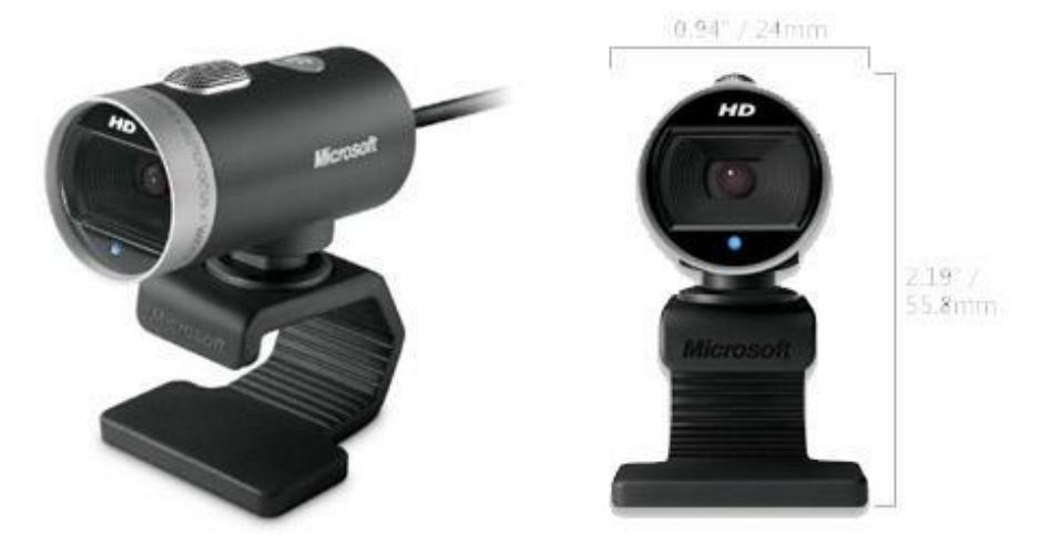
We use Microsft Lifecam's to capture images and videos and process in the main board. The image processing of our robots were programmed by the AForge classes in MS Visual Studio IDE. AForge.NET is a C# framework designed for developers and researchers in the fields of Computer Vision and Artificial Intelligence - image processing, neural networks, genetic algorithms, machine learning, robotics, etc.
The appearance of visual system is depicted in Fig .3.
2.4 Motion Controller
We are using CM-510 motion controller board produced by Robotis to save, play and control our motions algorithms.
2.5 IMU Sensor
Our robots use 3-Axis Gyro that are fully integrated 3-axis (X-Y-Z) gyroscope which integrates the IDG-650 and ISZ-650 chips onto one board. The communication with main board is done via I2C. The dimensions of the board are only 20 x 20 mm.
2.6 System Diagram
Fig.4 shows the basic YRA robots structure.
Overview
We are using Visual C#.NET environment to build interfaces with communication and data acquisition systems .Also we are now focusing in the communication between robots on game through a Game Controller.
3.1 Main Program
The program consists of 4 main blocks:
Hardware Interface :Contains all low level routines to access hardware of the robot including sensors and head actuators .
Vision :Contains image processing algorithms such as recognition of landmarks and other object .
Planning :Planning system of the robot is based on a multi layer, and multi thread structure.The layers are named Strategy, Role, Behavior and Motion.
Network :Mainly responsible for the wireless communication of the robot with the other robots or the referee box .This is done via WLAN.
3.2 Decision Algorithms
The main processor performs three tasks:
(1) a walking-pattern generator .Using the analytical inverse kinematics of legs and a parameterized leg-path generator is possible to easily perform omni-directional walking.
(2)some simple motions like standup, kick and block are developed with frame-based motion
(3) off-line decision-making algorithms are run to produce individual player's behaviors.
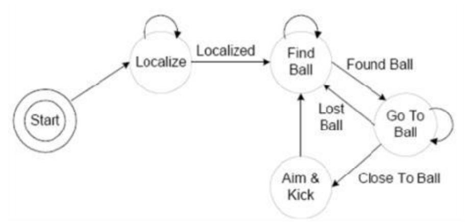
Off-line decision-making algorithms are run to produce individual player's behaviors. For example, a player behavior sequence is:
(1) find the ball.
(2) go close to the ball.
(3) get control of the ball.
(4) find opponent goal or pass the ball to a teammate.
(5) aligning to opponent goal
(6) shoot towards
(7) keep defensive posture.
A summarized graphic version of our decision algorithm is presented in Figure 5.
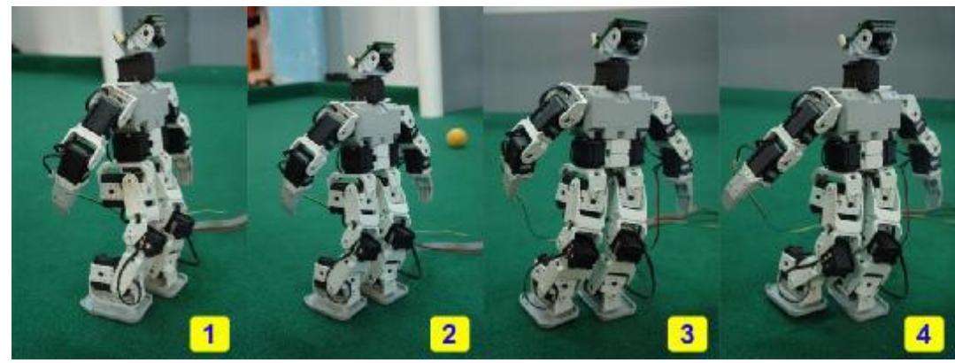
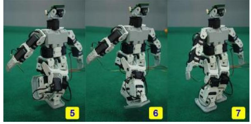
Kicking Ball
(See figures below)
5. Conclusion
In this paper we described on our system .Our system has some features .They are high mobility, strong kicks, well-designed control system, position estimation by one camera and user-friendly interface.
And we are working to design a new and optimized mechanical structure, and develop unique decision algorithms, and football coaching.
6. References
See reference list below.
References
- Robotis servomotors, http//:www.robotis.com/zbxe/dynamixel_en
- RoBoard RB-110, http://www.roboard.com/RB-110.htm
- RoBoard Module RM-G145, http://www.roboard.com/G145.html
- aiRobot :Team Description for Humanoid KidSize League of RoboCup 2009
- FUmanoid Team Description 2009
- Bogobots-TecMTY humanoid kid-size team 2009
- H.Miura and I.Shimoyama, "Dynamic walking of a biped," Int .J.Robot .Res., vol .3, no .2, pp .60–74, 1984.
- M .Rodrigues, F .Silva, V .Santos -Visual Tracking on an Autonomous Self-contained Humanoid Robot, The 11th International Conference on Clibing and Walking Robots and the Support Technologies for Mobile Machines CLAWAR2008, Portugal, Coimbra, 8-10 Sep, 2008.
- Microsoft Lifecam Cinema, http://www.microsoft.com/hardware/digitalcommunication/ProductDetails.aspx?pid=008&active_tab=overview