JEEP Team Description
Yuji Kawai, Takato Horii, Ryo Ninomiya, Jihoon Park, Yuki Fukushima, Dai Hirose, Ryuhei Sumita, Yuji Okuyama, Tomoki Kashima, Hiroki Mori, Minoru Asada
Adaptive Machine Systems, Graduate School of Engineering Osaka University, Osaka, Japan
Abstract This paper describes the current status of the humanoid soccer team JEAP which utilizes the commercially available humanoid platform Vision 4G with customized parts. A modular software architecture consists of three modules: the vision, the behavior, and the motion modules. We are developing selflocalization system now.
1 Introduction
Team JEAP originated from team Senchans[1] that participated in competitions of the humanoid league since 2002, the first year of the humanoid league. In 2006, the team changed its name to JEAP[2], which is an acronym for JST ERATO Asada Project [web: www.jeap.org]. The project had been supported by the Japanese Science and Technology Agency (JST). Although this project was finished in March 2012, we continue to use this name. A main goal of this project was to understand the cognitive developmental process of humans based on synthetic approaches with humanoids. The project adopted Vision 4G as a research platform, and the RoboCup humanoid league is a good testbed for this purpose. The research issues are human-like cognition of environment, motor learning for the game, cooperative planning with teammates, advanced dynamic biped walking and so on.
In this article, we describe hardware specifications in section 2. The software design is given in section 3.
2 Robot Hardware
Since the RoboCup 2007, we have utilized the Vision 4G robots. They are fully autonomous robot, manufactured by Vstone Co.,Ltd..
The motors of the Vision 4G robots are developed in order to generate the stronger torque stably. The covers of the motors are made from aluminum to assist its heat dispersion. Therefore, they could continue to play without breaking down for a longer time.
Fig. 1 shows the robot's appearance and DOF configuration. Figs. 1 (a) and (b) are photographs of the whole body of the robots. The two tube in front of its torso and the object on the back are attached as a cushioning when the robot falls down. The robots have Logicool Webcam Pro 9000 camera to capture high resolution images. Fig. 1 (c) shows the robot's head including the monocular camera. Although it seems to have two cameras, the big right eye is a fake. A VisiON 4G robot has 22 degrees of freedom and pan-tilt cameras (see Fig. 1(d)).
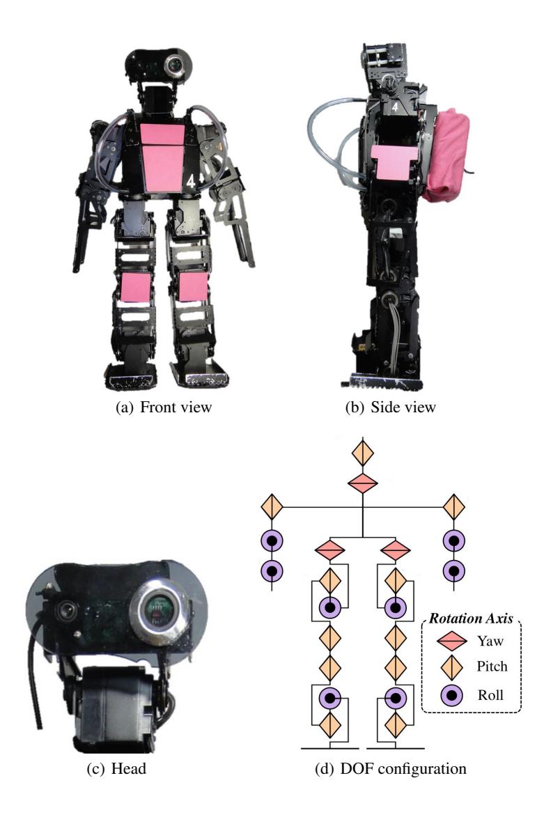
Table 1. VisiON 4G hardware specifications
| VisiON 4G | Main controller | Sub controller |
|---|---|---|
| Height (mm) | 465 | |
| Weight (kg) | 3.2 | |
| DOF | 22 | |
| Actuators | VStone Servo | |
| Camera Type | Logicool Webcam Pro 9000 | |
| Controller | Main controller | Sub controller |
| CPU | PNM-SG3 | VS-RC003 ARM |
| ROM | 16GB (Flash HDD) | 512 KB |
| RAM | 512 MB | 40 MB |
| OS | Linux | None |
3 Modular software environment
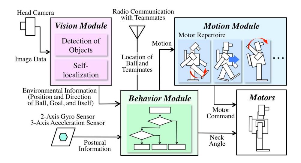
The software of the robot consists of three modules: the vision, the motion, and the behavior modules. These three modules perform in parallel during the game. The vision and behavior modules are programmed on the main controller. The motion module works on the sub controller.
Fig.2 shows the overall system of the software. The vision module detects positions and directions of the ball, the goals and itself from image data. The behavior module selects an appropriate pattern of motions based on information from vision module. The motion module memorizes the motor repertoires coded as joint angles. The motor commands are selected based on the orders from the behavior module, and are executed by motors.
The rest of this paper is the explanation of each modules
3.1 Vision Module
The vision module has two functions: detecting of objects and self-localization. This module sends the environmental information (e.g., the location of the ball, the goal, and the robot), which are processed from image data captured by the camera, to the behavior module. At first, areas of objects are detected by image processing. Secondly, the selflocation and distance between the robot and the ball and the goals are calculated.
Detection of objects
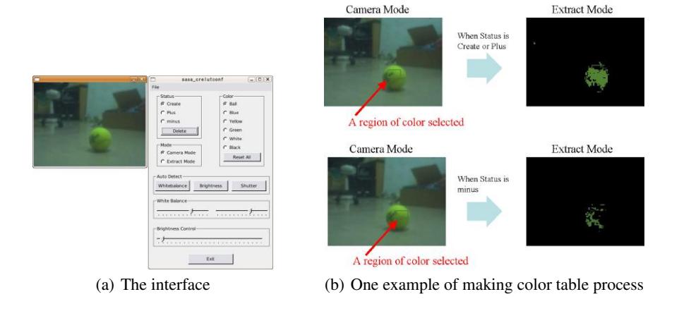
We developed a library for the image processing as a vision module. Since the luminance and pixel values of colors sometimes change because of the shadow and lighting condition, it is necessary for robot to know the range of color variation. For this purpose, we implemented a GUI application for setting color variation in vision module (see Fig. 3(a)). By using this system, we can make a color table by adding or subtracting the range of the values of pixels before the game (see Fig. 3(b)). The robot uses it during the game and detects the areas of objects robustly.
Self-localization
We are developing self-localization system using field lines based on the Particle filter algorithm. This filter is widely used to detect self-position for the mobile robots (e.g., [3], [4]). In our system, robot's location is estimated in the following procedure:
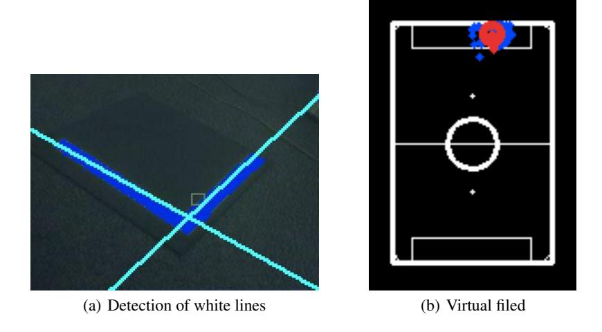
- The robot detects the white lines by Hough transform algorithm[5]. Fig. 4(a) shows the result of the line-detection system. This algorithm transforms groups of white-colored pixels in a image to the lines.
- The likelihood in each particles set in the virtual field is calculated. The particles in the virtual field are shown in Fig. 4(b). The small dots and the red circle are the particles and the robot's position, respectively. The robot's location is calculated as a average of location of particles. The likelihood is solved by the similarity between the captured lines and the calculated lines in the virtual field.
- The particles are moved toward the particle with the most likelihood.
- Step 2 and 3 are repeated until convergence.
3.2 Behavior Module
The behavior module determines an appropriate motion out of the motor repertoires depending on the environmental information, the self-posture.
The behavior module sequentially receives the information of the field (the ball, the goals and its own location and posture) from the postural sensors and the vision modules. VisiON 4G has the 2-axis gyro and 3-axis acceleration sensors. The robot's postural information whether robot is down or not is detected by threshold processing of these sensory data. Furthermore, the behavior module transmits and receives the environmental information via UDP communication. This communication enable the robot to act cooperatively. Based on the information, the robot selects an appropriate motion from motor repertoires, such as kicking, walking, throwing, and so on.
These plans of the motions can be changed depending on roles of the robots. We assign the role (goalkeeper, offence or defence) to each robot.
3.3 Motion Module
The motion module receives the order of motions from the behavior module, and submits its motor commands (i.e., joint angles) to the motors. This module memorizes motor repertoires which consist of patterns of joint angles.
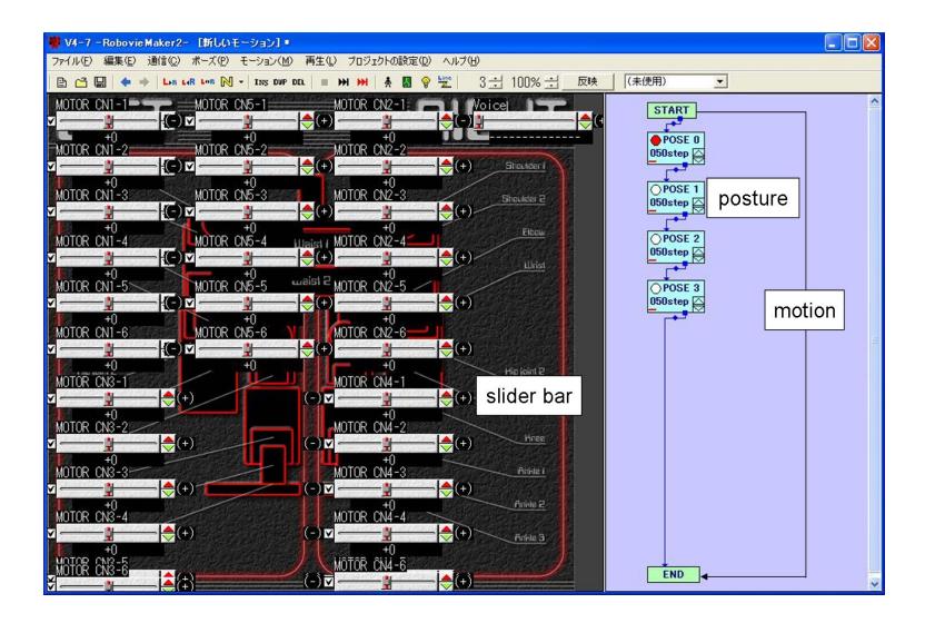
In order to create these motor repertoires, we use RobovieMaker, which is a software developed by Vstone. Fig. 5 shows the development environment by RobovieMaker. Each value of slider bars corresponds to the joint angles of the motors. Robot's postures are made by these slider bars. The box on the left side means a postural data. These boxes are linked like flowchart to create the motions. The postures between the postures made by the slider bars are automatically interpolated. The RobovieMaker enables us to create the motions more easily.
References
- Norbert Michael Mayer, Joschka Boedecker, Masaki Ogino, Masaaki Kikuchi, Rodrigo da Silva Guerra, and Minoru Asada. Osaka University Team Senchans 2005. In RoboCup 2005 Symposium papers and team description papers CD-ROM, 2005.
- Norbert Michael Mayer, Masaki Ogino, Rodrigo da Silva Guerra, Joschka Boedecker, Sawa Fuke, Hiroyuki Toyama, Ayako Watanabe, Kazuhiro Masui, and Minoru Asada. JEAP Team Description. In RoboCup 2006 Symposium papers and team description papers CD-ROM, 2006.
- D. Fox, S. Thrun, F. Dellaert, and W. Burgard. Particle filters for mobile robot localization. In A. Doucet, N. de Freitas, and N. Gordon, editors, Sequential Monte Carlo Methods in Practice. Springer Verlag, New York, 2000.
- T. Rofer, T. Laue, and D. Thomas. Particle-filter-based self-localization using landmarks and directed lines. RoboCup 2005: Robot Soccer World Cup IX, pages 608–615, 2006.
- R.O. Duda and P.E. Hart. Use of the hough transformation to detect lines and curves in pictures. Communications of the ACM, 15(1):11–15, 1972.