Plymouth Humanoids Team Description Paper for RoboCup 2013
Arron Griffiths, Clare Simpson, Paul Eastham, Alex Smith, Guido Bugmann, Chenguang Yang, Peter Gibbons, Phil F. Culverhouse
Centre for Robotics and Neural Systems (CRNS), School of Computing and Mathematics, Faculty of Science and Technology, Plymouth University, Plymouth, UK
www.plymouth.ac.uk/robotfootball
Abstract This team description paper provides an overview of the Plymouth Humanoid kid size robot which will be used in RoboCup 2013. The small humanoid robot has undergone a lot of development since RoboCup 2012, the first ever RoboCup competition Plymouth University has entered in. The design is based around the platform that won the marathon and came second in the sprint in FIRA 2012 RoboWorld Cup. Last years robot comprised mostly of Robotis standard Bioloid platform parts. This year we have moved away from Robotis and designed our own hardware. However, several components on the robot still include dynamixel servos. The torso, which is designed and built in house, is made from 3mm black Perspex which is light weight, durable and easy to modify. This holds the Plymouth Humanoid Tartarus Atmel Xmega microcontroller board, for low level servo and peripheral control. Higher level control includes: vision processing, high level servo control, localisation and game play which is coordinated by the Trimslice-H miniature desktop PC. The vision system is captured using a standard Sweex HD USB webcam. With continuing hardware and software development as well as some previous RoboCup experience from dedicated staff, students, technicians and researchers we hope to achieve a higher standing result in 2013.
1 Introduction
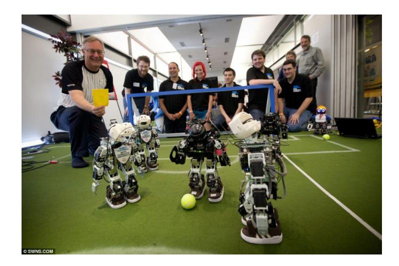
The Plymouth Humanoid robot is a low cost small bipedal robot platform that is regularly updated to use the latest embedded computer technology, state of art IMUs and cameras. Most of the electronic systems are engineered in house. Plymouth University has been competing in the small bipedal HuroCup league FIRA RoboWorld Cup since 2008; Fig. 1 shows Plymouth Humanoids competing against the Plymouth University undergraduate team at FIRA 2012 in Bristol. In 2011 we came first in the sprint and marathon and in 2012 came first in the marathon and second in the sprint. Since the success in 2011 a separate team has been formed to use the fundamentals of these events to design a football playing kid size robot. Plymouth Humanoids entered RoboCup in 2012 for the very first time, coming in 16th place overall.
2 Hardware
As a University team which researches and develops both hardware and software, we have a good understanding of how hardware can be used to improve a platform. Over the last year a major improvement in the electronics within our platform has been undertaken. The follow devices have been implemented on our humanoid robot and will be used in the upcoming RoboCup competition.
2.1 Trimslice-H
The Dual core ARM A9 processor board has been embedded with Ubuntu and our robot framework. This board has full wireless capability, which communicates to the RoboCup Referee enabling the platform to be full autonomous once running.
Tartarus Board
The current development of the new Tartarus board at Plymouth University has been undertaken due to short comings with previous servo controllers, such as the CM700 (Robotis). The board has been primarily designed as a real time servo microcontroller; secondary functionality includes full power regulation for the robot platform. The output voltage capabilities of the board includes: servo voltage (5A), 12V (2A), 5V(1A), 3.3V(1A) and also includes built in battery hot swap system when an external source is providing power to the robot.
The board also features three USART buses; these enable the robot devices (servos and sensors) to be separated out with parallel communications. This enables the time period for sending and receiving data to be significantly reduced, allowing for more data flow and a faster closed-loop feedback system.
2.2 Inertial Measurement Unit (IMU) Board
The IMU system has been developed within the university as a stand-alone device utilising a standardised TTL communication bus, which enables it to be available for research and use by other groups. It is comprised of three single axis MEMS gyroscopes and one 3-axis accelerometer, with a dedicated microcontroller to increase resolution for integration of raw data output, reducing computational load on the main robot controller. The gyroscopes are provided by Silicon Sensors who manufacture military grade inertia sensors, giving a basis for high precision, high reliability inertial information.
The sensor is placed within the centre of mass, giving the ability to provide navigation odometry and inertial feedback, to improve stabilisation. Using this, a stable dynamic gait can be improved upon, increasing walking speed and manoeuvrability, such as side-stepping and walking backwards. The low drift yaw gyroscope provides directional information so each individual robot has knowledge of its orientation. Due to changes in rules from 2012 to 2013 regarding goal colours, this method ensures that correct goal location and scoring is achieved.
3 Software
3.1 Robot Framework
Plymouth Humanoids has been developing a robot framework for use on our hardware platform. The software architecture has been structured in a modular way, which has a unified format. This allows for easy interlinking of expandable software modules, avoiding duplication of code. The diagram in Fig. 2 shows the key modules within the framework and how they are separated and linked with one another. Each block is described below.
Olympus – Primary vision, strategy and communication (wifi) module, situated on the on-board embedded Linux micro-PC.
Hermes – A communication protocol module, which interlinks the high-level controller with the low-level microcontroller. This also includes a human interface for debugging and development of the framework.
Robot Controller – Framework GUI which allows for debugging and development of key areas within the framework such as calibration, pose editing, gait adjustment, data logging and feedback.
Hades – The low-level embedded micro-controller software which handles the real time control of servos and sensor modules; also channelling kinematic and sensor data back to the higher-level controller to aid decision making.

3.2 Vision System
V4L – FUmanoids A dramatic improvement within our vision system is thanks to the implementation of the open source libraries provided by the FUmanoids team, Berlin [2]. These libraries have enabled us to have direct access to our camera, allowing for improved tuning of various camera parameters, i.e.
saturation and white balance. This has enhanced our tolerance in differing lighting environments, making the system more robust. These libraries have been integrated into our framework and form the basis of our video capture system.
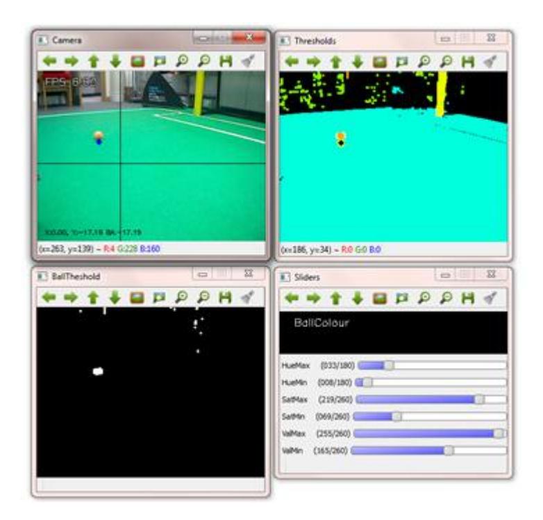
Thresholding and Object Detection Vision thresholding of multiple colour objects has become more reliable due to the improvements achieved through the implementation of the V4L system. Fig. 3 below shows a calibration GUI view of the high-level embedded framework. Key features include (clockwise from top left): Live robot POV, combined view of multiple thresholds, calibration for each object and threshold view of each individual object.
Ball Detection The fundamental principal of ball detection lies within finding an orange ball on a green pitch; this is achieved using a layer of robust circle detection and polygon matching. This enables the robot to distinguish orange objects within the correct environment and improves the probability of correct ball detection. Once a target ball has been identified, with the use of kinematic feedback from the angle of the head and the height of the robot, the distance to the ball can be calculated. This is fed into the high-level strategy, allowing the robot to decisively navigate to the ball.
Goal Detection The goal is recognised in a similar manner to the ball detection, where two colours are identified the yellow of the goal and the green of the pitch and then combined. This is then fed into a shape recognition algorithm to detect the presence of a post, crossbar or combination of both. This information is also triangulated in a similar way to ball detection, so the distance to the goal is known. This is then fed to the strategy system, enabling the robot to make an approach onto the ball with relevance to the goal position, therefore allowing the robot to get to the ball and make a high probability attempt at scoring a goal.
3.3 Strategy System
The Strategy system of the robot has evolved over the last year with significant improvements mainly in path planning and decision making; trying to move away from a very basic state machine towards a more dynamic timed behaviour system with memory allowing for more flexibility in decision making.
Sensory Feedback The higher (vision) and lower (servos and IMU) level sensory feedback is fed into the strategy system to produce a two dimensional map of the field of play. The information that is acquired from the object detection is combined with the kinematic feedback from the servos; this information is averaged over time to provide a more confident sensory feedback of where the ball and goal lie within the field of play. This current system will hopefully be improved with the use of Kalman filters before RoboCup 2013.
Time-out Behaviour State Machine The strategy system was based on a simple state machine, which has been improved upon with the integration of time-out behaviour. This means that certain state behaviours are allowed to run for a finite time period before being re-evaluated by the current environmental situation. A number of states can co-exist at the same time, allowing a more behavioural structure to generate the robots final action. An example of this would be the ball chasing routine, which has a singular task to keep the ball the focus of the robots attention which co-exists with the localization routine, which requires to robot to acquire a fix from markers (goals and lines) when the positional probability drops below a set threshold.
3.4 Dynamic Gait
The Plymouth Humanoid robot platform is still using our own dynamic gait system. This generates sinusoidal motion based on a two link manipulator, which uses a kinematic model to produce locomotion. More information on this method can be found in [1].
The gait this past year has been improved upon to help optimise the current dynamic system; these areas include calibration and servo speed calculations.
Servo Speed Calculations The servo speed calculator is used to smooth the kinematic motion of the servos through the sinusoidal motion of the dynamic gait. This allows the legs to move in a constant velocity which increases stability by improving pendulum motion and minimising jerk.
4 Calibration
Each Plymouth Humanoid is hand built and has small mechanical inaccuracies; therefore all servos need to be individually calibrated for every robot to make sure the robots are all uniform and behave in the same way. Calibration affects the locomotion and odometry of the current bipedal system such as the gait, pose based functions (get-ups, kick) and ball position based around calculations from a kinematic chain.
Last years calibration procedure involved estimating if one or more of the servos is not at its goal requested position; this was achieved visually. The servos were then adjusted accordingly and those offsets are used in the transmission of the commands to the servos. The problem posed using this method is that the operator must make a decision based on visual evidence, on what leg, servo or combination of servos to change. This year a new calibration procedure has been produced where the robot is fixed into a mechanical frame construction made from Easy Fix (preformed materials) aluminium tubing. This ensures that the robot legs will be in the exact desired coordinates (in X, Y and Z planes). A GUI has been designed which allows the user to calculate the servo positions based on an input of link lengths and kinematic calculations. This is then compared to the feedback of the actual (real time) servo positions and the corresponding offsets are stored in an XML file.
5 Summary
Plymouth Humanoids are commited to participation in RoboCup 2013 Kid Size humanoid league competition. A significant amount of progress has been achieved to improve the system in light of issues and revelations brought up during the 2012 RoboCup event. The main improvements have been in hardware and platform stability, creating a more robust robot for game play. Planned future improvements include upgrading the body shell to aluminium to give better structural strength, improved sensory feedback using multiple IMUs, an improved dynamic gait and high quality cameras to improve robustness of visual feedback. Each member of the team has knowledge of the rules and regulations of RoboCup and one team member will be available to referee during the competition. Special thanks go to the FUmanoid team, for use of their open source V4L libraries.
References
- Gibbons, P., Culverhouse, P., Bugmann, G., Tilbury, J,. Eastham, P., Griffiths, A., Simpson, C.: Plymouth Humanoids. (2012)
- Berlin United FUmanoids V4L: http://www.fumanoids.de/publications/coderelease/