Team RoBIU
Abir Atur, Amitay Nachmani, Benzion Suwid, Elad Stern, Gil Meiri, Itzik Tabibian, Kfir Ozeri, Omri Attoun, Ori Zaig, Oriya Daniel, Rotem Frenkel, Shai Etsion, Shlomo Birenboim, Tal Attar, Tomer Glixman, Uria Vidal, Rafi Amsalem, Dr. Eli Kolberg
Bar-Ilan University, Faculty of Engineering 52900 Ramat-Gan, Israel
Abstract This paper presents the hardware and software layers of the kidsize humanoid robots of RoBIU team. The paper describes the robot's specifications and the main aspects of our project, including real-time image processing and object detection, sensors and camera based localization, high-level behaviors implementation and robot agents intercommunication.
1 Introduction
Team RoBIU achieved significant results in last year's competition. We hope to retain these accomplishments and achieve even more. Notable this year, we improved our decision-making algorithms and the code in order to achieve greater efficiency. RoboCup 2013 will be a great setting to observe and study our enhanced software and team performance. We hope to fulfil our university's slogan ''Tradition of Excellence'' by advancing even further in the competition.
Team RoBIU is made up entirely of undergraduate seniors, as a part of their senior year capstone project, under the academic supervision of Mr. Rafi Amsalem and Dr. Eli Kolberg. The purpose is to let the students experience working in a large-scale project which incorporates challenges such as strategics planning, coping with deadlines, mediating between sub-mission groups and managing the development of software. Team RoBIU would like to commit to participate in the RoboCup 2013 Humanoid League competition. Team RoBIU is able to provide students who have sufficient knowledge of the rules to serve as referees.
2 Robot Overview
.
2.1 Mechanical Design
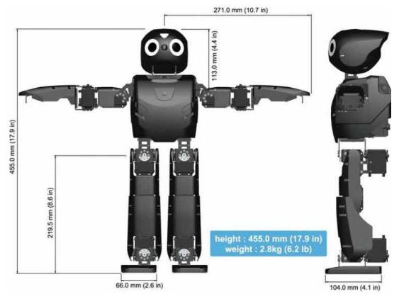
The robot we use is the DARwIn-OP [1]. Fig. 1 shows the dimensions of the robot. The motion mechanism consists of 20 degrees of freedom, divided as 6 DoF for each leg, 3 DoF for each arm and 2 DoF for the head. The robot's weight is 2.8 kg and its height is 45.5 cm. The robot's walking speed is optimized for real-time adjustments maintaining fast and stable locomotion.
2.2 Actuators
The robot uses Robotis' RX-28M Dynamixel motors[2]. Each servo motor has its own microcontroller, allowing for a network of servos to be controlled by a single microprocessor via a TTL network. The RX-28M weights 72g, has a resolution of 0.29 degrees and a gear reduction ratio of 193:1. The RX-28M provides the feedback of temperature, position, load and input voltage, indicating an an overheat and emergency shutdown when the temperature exceeds its range.
2.3 Sensors
The robot is equipped with a 3-axis LYPR540AH gyroscope and a 3-axis ADXL335 accelerometer that enable a robust and stable locomotion. The robot has a 2MP HD Logitech C905 Camera, with a 640x480 resolution, providing a visual information that is used for object detection and localization. The robot also uses pressuremeters - 4 FSRs in each foot.
2.4 Controller
The main controller of the robot is a CompuLab FitPC2i board featuring a 1.6 GHz Intel Atom Z530 processor with 1GB of RAM. The FitPC2i has a WiFi enabled for team communication.
As mentioned before, the robot also has a microcontroller board - the CM-730. The CM-730 is a management controller, with an ARM CortexM3 processor. The CM-730 connects between the servos and the FitPC. The CM-730 is connected to the FitPC via a USB port. The camera is connected to the FitPC via a USB port as well.
3 Software
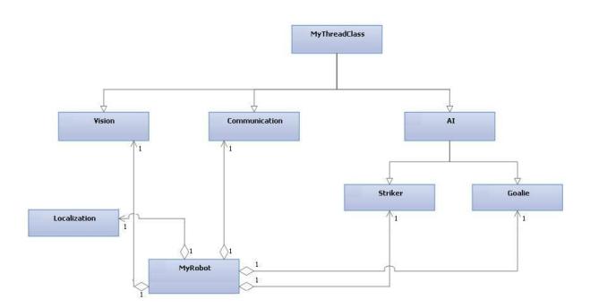
The software contains several models (see Fig. 2):
- Vision Model for image processing.
- Localization Model that receive inputs (like objects and distances) from vision and generate the robot's location.
- Motion that manage the robot's walking and actions.
- Communication that handle the communication between robots.
- Artificial intelligence that includes the striker and the goalie's behaviors
In order to control and access all those models simultaneously we used multithreading. Although our CPU has only one core which doesn't allow us to actually run different code sections in parallel.
3.1 Vision
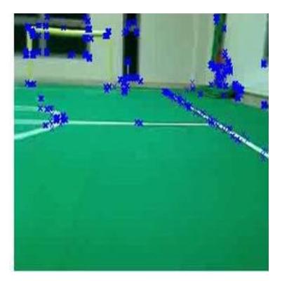
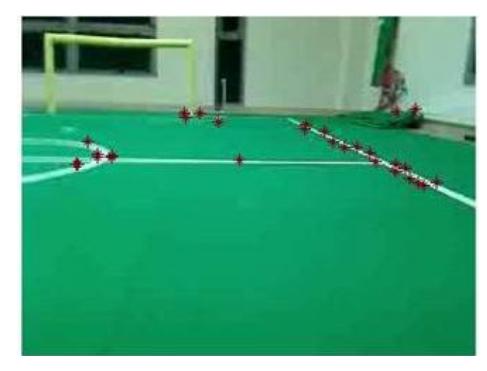
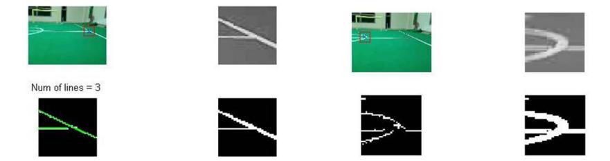
We use the Logitech C905 webcam as our camera. We use it to recognize and measure distance and angle from the ball and various landmarks on the field, for the purpose of localization. Landmarks on the field comprise of white line junctions and goal posts. In order to speed up our search for these landmarks we use the FAST corner detector[3][4], in order to find potential points of interest as can be seen in Fig 3(a). This is done on a black and white image. We use the color of these points in the color image to filter out points that don't meet some basic criteria (Fig 3(b)). Then the picture is cropped around the remaining points of interest. This cropped image is analyzed in order to find out if it holds genuine ball/landmark which will be used for further processing (Fig. 4). If this is the case, we classify the landmark, ball or goal post into its correct type, and measure the distance to it. The resulting data is transferred to the localization algorithm.
3.2 Localization
As was done previously, the localization uses Particle Filtering, a.k.a. Sequential Monte Carlo method. As inputs we track the robot's steps and use objects that are detected by the camera. Using the filter allows us to make an educated guess of the robot's location and heading, relative to fixed objects in the field (goal posts and line intersections).
Last year, the only fixed objects in the field that we were able to use were the goal posts and localization side poles. This resulted in six unique objects in the field.
This year, the goal posts have become identical and the side poles have been removed entirely, so we've had to compensate for these changes by supporting all line intersections on the field, as well as the goal posts. Supporting line intersections results in a total of fourteen (five unique and nine identical) fixed objects in the field. Fortunately, this ultimately results in better algorithmic performance, for faster convergence of robot's actual location.
Breaking field symmetry is done by locating a "reference point" outside the playing field prior to each match and searching for it occasionally when in doubt as to attack direction.
3.3 Motion
Last year, the biggest concern in the motion section was robot stability in motion. This year, we've managed to enhance the robot's mobility in two aspects: speed and stability. Achieving these improvements required many tests following each change to basic movement configuration. Additionally, we examined the best way to reach the ball in terms of speed and algorithm efficiency. In order to increase speed, we made the robot lean forward and bend a little. This change successfully increased the robot's maximum speed to approximately 40 cm per second, without falling. Improvements to the algorithm were made by changing the implementation of walking towards the ball or any other coordinate in the field.
3.4 Behavior
The "Brain" of each robot determines the desired behavior in accordance with two main considerations:
- environmental information: includes ball position etc. self team-member posture and position in the playground.
- team-decisions: includes simples behaviors such blocking an opponent from striking, and complex behaviors such coordinating each team member current rule corresponding the game situation and sharing tasks between team
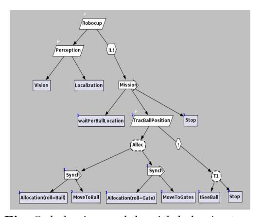
Usually, such behavior modules are implemented with state machines; every behavior-element is represented by a state, and the interaction between them is represented by synchronic/asynchronic different communication-links. In the last years there is a trend of moving from FSM toward behavior trees.
Behavior trees are acyclic-graphs that represent the behavior elements (tasks) and the desired flow between them. In another words, with behavior trees one can define directly the task sequences and the flow between the tasks. With FSM it is necessery to figure out which events/triggers will lead to the desired flow. Additionally, FSMs are less scalable and expose to more fatal patterns (as deadlocks, for instance) when working in-parallel with other FSMs.
Therefore, our team decided to build the behavior module with behavior trees, and for that we are using the "cogniTAO" development environment. cogniTAO is a JAUS-enabled, high-level control component which utilizes modern robotics control paradigms.
It allows for:
- Coordination between multiple robots working in teams.
- Tight coupling between the decision-making components.
- Visual modeling components.
- Smart threads system management.
Once configuring the behavior tree in cogniTAO, and integrating its tasks with the code-elements it's represented, it is possible to compile the code-elements only once, and then change the interaction between tasks via cogniTAO (that generate corresponded XML file). This ability is highly important in area where making behavior-changes rapidly and safely is required.
Our goal is to create well-defined trees, that fit all of the situations our team can encounter with.
Striker
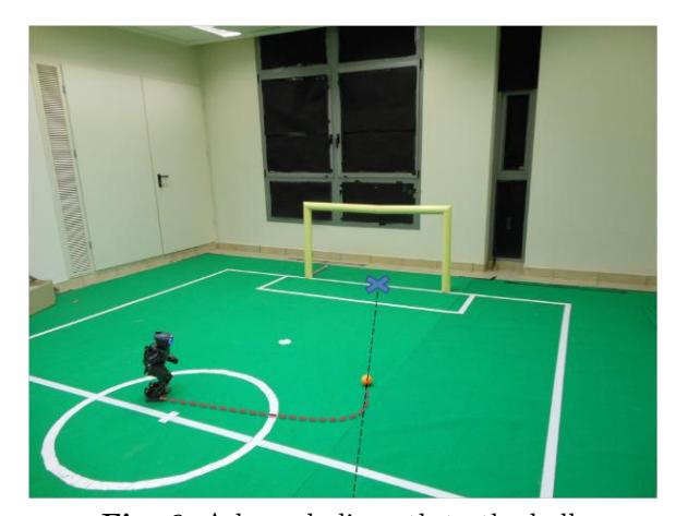
In this division, we try to improve the striker behavior and its abilities. We strive to improve the time that takes the robot to kick. Until now, the robot went right to the ball, and then , start to do a small sideways steps around the ball (we call this process as: ''rain dance'') until it is positioned in the right angle, and only then , it kicks. The "rain dance" takes a lot of time. So, we work on a plan that will help us to abandon the "rain dance" completely. In this method the robot will walk to the ball, in a way that position it in the right angle to kick from. This method, makes the robot walk in a hyperbolic way:
As can be seen in the figure above, the robot walks in a straight line following the path marked with dots until it reaches a place we calculated according to lab test results, and from then, the robot starts to walk with an angle, such that the robot gets to the ball facing the right direction. In addition, we improved the strength of the kick, by testing the optimal distance of the robot from the ball. In the future, we will work on team work behaviors of the striker. We intend to implement a pass between the strikers, and to identify the opponents, which will add an input to the robot's decision making.
Goalie
Last year's goalkeeper was probably the best in the tournament.
This year mission was to stabilize his walking, improve the time elapsed from identifying the ball to kicking it (hyperbolic path to the ball), make the goalkeeper go out toward the opponent's striker and adding some "tweaks" to the existing code.
The basic decision algorithm is:
- initialize
- if ball is coming toward you jump to the ball.
- if the ball is in the danger zone send the ball away.
- 3.1. if ball reached kick the ball, else go to step 5.
- step aside in order to be positioned in the ball's path.
- go back to the goal, position yourself in the right place and return to step 2.
4 Prior Performance in RoboCup
Team RoBIU was founded in 2010, consists of only undergraduate students from the Bar-Ilan University Faculty of Engineering. The first team which used to be called BI-Forward couldn't participate in RoboCup 2011 due to security constraints regarding travel to Turkey. Last year's team made it to the quarter finals of RoboCup 2012 which considered a very impressive achievement because it was team RoBIU' first participation in RoboCup.
5 Conclusion
In this paper we've introduced the mechanical structure and software design of our robot. It is the second year of the development of our software, and we keep on trying to improve many aspects of the project. We look forward to participate in the RoboCup competition this year, and we hope to contribute it a significant part.
References
[1] DARwIn-OP Brochure, http://darwin-op.springnote.com . [2] Robotis Product Information, http://www.robotis.com . [3] E. Rosten and T. Drummond , Fusing points and lines for high performance tracking. IEEE International Conference on Computer Vision, 2005. [4] E. Rosten and T. Drummond , Machine learning for high-speed corner detection. European Conference on Computer Vision, 2006.