VATIO UP
Efraín Hernández, Roberto Carlos Ramírez, Jonathan Alcántar, Alberto Petrilli, Andrea Santillana, Antonio Salvador Gómez
Robotics Lab, Universidad Panamericana Campus Guadalajara, Jalisco, Mexico
Abstract This document describes the hardware and software of the Humanoid Robots Team VATIO UP, designed and manufactured by students, able to play soccer autonomously to participate in Robocup kid size humanoid league. This is the fifth generation of robots developed and designed by the team Pioneros Mexico, and this was the first Mexican team entry in humanoid league of Robocup.
Introduction
Robotics is rapidly becoming one of the leading fields of science and technology: we can forecast that in the XXI century humanity will coexist with the first alien intelligence we have ever come into contact with robots. This is certainly due to new needs and expectations humans have from robots. It seems that requirements for factory automation, assembly, and industrial process control have been reasonably fulfilled. However, new fields such as service and assistive robotics require different kinds of robots that humans can interact with. The actual challenge of robotic is to equal the mobility of the human beings, making movements of great complexity and precision, and to be more intelligent.
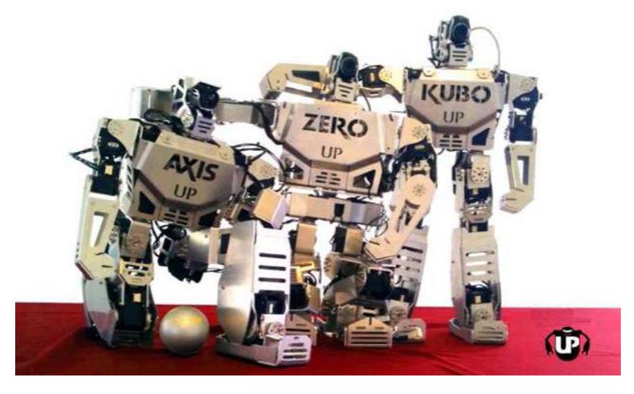
With this project we pretend to contribute in robotic science for applications that improve people quality life, for example the development of prosthesis with the objective and possibility that an invalid person could walk again and recover great part of mobility. With this background context, we have encouraged the construction of our own research platform for studying robot locomotion and sensing, thus, our VATIO-UP Humanoid Robots are capable of bipedal walking and performing human-like motions (Fig.1).
Notice of commitment: The team VATIO UP commits to participate in RoboCup 2013 in Eindhoven, Netherlands and to provide a referee knowledgeable of the rules of the Humanoid League to serve during the competition.
General Architecture
VATIO-UP Humanoid Robots are a self-contained prototype with a head, a torso, two arms, and two legs. It exhibits 21 DOF powered by a total of 21 actuators. The head consists of a pan-and-tilt structure (2 DOF). Arms add 6 DOF, 3 DOF each: shoulder, arm, and elbow. Head and arms are mounted on a torso. Finally, the legs add 12 DOF, 6 DOF each: one at waist level that allows rotation of the entire leg, two at the upper part, one at the knee, and two at the foot. A color video camera is mounted on the head's pan-and-tilt structure.
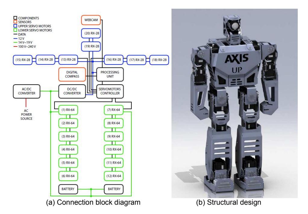
Both batteries and processing unit are to be on-board the structure. Fig. 2(a) shows VATIO-UP Humanoid Robots connection block diagram, while its physical structural design is shown in Fig. 2(b). The main structure involves four types of blocks connected each other by electrical and data lines. These blocks represent components, sensors, and the upper and lower servomotors, which form together the mechanical structure of the robot. On the upper side, there are eight servomotors RX-28 (blue), three for each arm (3 DOF) and two for the head (2 DOF), while in the lower side there are 12 servo motors RX-64 (green): six for each leg (6 DOF). Since the servomotors on the lower side require a higher torque (because of the weight they have to move), a higher voltage needs to be supplied (green line), while on the upperside, the torque is minimum and a lower voltage (blue line) can be supplied.
Two types of sensors (orange) are used to have feedback from the outer world: a webcam placed on the head and a digital compass located inside the chest. This last one includes magnetic sensors and accelerometers that send information to the processing unit to keep the robot's balance and let him know if it is lied down either up face or down face.
Likewise, instructions for the servomotors are sent through the servomotor controller by the processing unit. Data are sent by serial connection (black line) through five data lines (one for each limb and head), even if some at the middle of the chain are not required to move. The main power source of the robot is taken either from the batteries or by plugging it directly to the AC power source (red line).
Hardware
Humanoid Robots are entirely made from two types of aluminum alloys: 3105-H22 and 3003-H23. The first one is malleable and is used for the most complex links containing folds. The second one is rigid and is used for the simpler links. H22 aluminum links were laser cut with a ±2 micron precision, folded with hydraulic press, and welded using gas tungsten arc welding. H23 aluminum links were manufactured with a three-axis CNC machine. Actuators powering the robot's joints are servomotors of type RX-10, RX-28, and RX-64 from Dynamixel [1]. All three provide a step precision of 0.29± while torque is 10, 28, and 64 kgfcm, respectively. RX-10 servomotors are used for the head, RX-28 for the upper limbs, and RX-64 for the waist and lower limbs. A processing unit running Linux and C++ is used for image processing and servomotor control. This module is located inside the robot's torso. A set of batteries are located at the feet. Robot's main physical specifications are listed in Table1.
Table 1. Physical specifications of VATIO-UP Humanoid Robots.
| Height | 56 cm |
| Width (arms closed) | 33 cm |
| Width (arms opened) | 72 cm |
| Depth | 16 cm |
| Arms' length | 24 cm |
| Legs' length | 32 cm |
| Total mass | 5 kg |
Software
The whole software of the robot is implemented in C++, using event handler and multithreading tools, it helps because we have several systems running simultaneously, and each one have different importance level and hardware requirements; in addition, depending of the situation only some systems are need to be activated, e.g. during a game we need different systems that during motion modeling, demonstration or calibration.
As a human being, we have separated the functions of the robot in several systems: locomotion, video processing, reading sensors, controlling actuators, wireless communication, kinematic modeling, graphical interface and behavior control. In addition, each system has mechanisms to identify errors in themselves, for example, identify if a sensor or actuator is not working properly, generate alerts, and try to solve the problem.
Electronics
Each robot is now equipped with Pc Pro Intense-PC PRO single board computer [2] as the main computational unit, that has is a full featured PC single board computer, tiny and power saving. This CPU is an with Intel Core i7-3517EU @ 1.7 GHz, 6GB DDR3-1600, 30 GB SSD, and using Linux Mint as OS. Mother board has several interesting features which make it ideal as a brain for humanoid robots. These include low weight and power consumption, direct connection by USB 2.0 for all de sensors, camera and controllers. The board also supports Wireless LAN 802.11b/g/n WiFi which is used for communication with the referee box, and actually is in development the communication between the robots.
The UM6 Ultra-Miniature Orientation Sensor [3] combines sensor measurements from rate gyros, accelerometers, and magnetic sensors to measure orientation at 1000 Hz. Angle estimates are available as Euler Angle or Quaternion outputs, and it has direct connection to the main controller (fitPc2) by USB 2.0. This sensor is very useful to determinate the position of the robots inside the field but is used in parallel with the vision system to have redundant information. The Dynamixel servomotors controller is the CM700 [4] because this device can have serial communication in five different lines simultaneously, one for each extremity. This controller is also connected to the main controller by USB 2.0 with the communication module LN101, both controllers from Robotis [5]. A Logitech Webcam C300 [6] is mounted in the head with a pan-and-tilt structure to aquire image data from the outer world. Each robot has a package of batteries that provide power to have 20 minutes of autonomy at full charge.The robot has two packages of rechargeable LiPo batteries [7] of 18.5 volts at 25C 750mAh, one in each foot.
Robot Behavior Control
The behavior control is based on the concept of Finite State Machine, and implemented in C++, where we use several state unknowns. Basically there are three layers: Operation Mode, Define Target and Individual System Control, but each layer may have sublayers like a hierarchy tree; for example, at layer Individual System Control there is the Locomotion sublayer, at layer Locomotion there is the Walk Forward sublayer, and at layer Walk Forward we have the DS-ZMP state (Double Support - Zero Moment Point). This kind of implementation makes very easy to add, remove or even improve states at any level of the hierarchy tree. If we want an excellent performance in the game, we need a good Behavior Control; but we also need a great Locomotion System; to achieve this, we solved analytically the simplified differential equations system (assuming constant inertial tensors) obtained from the 3D dynamic free diagram body of the humanoid, it gives us a very good approximation to the ideal trajectory of the CoM (Center of Mass), then we apply inverse kinematics to the legs, but it changes the CoM in the model, so we use the gradient descent algorithm to approach again to the ideal trajectory; finally the robot use the arms to reduce to the minimal the moment generated by the variability of the inertial tensors. In addition we solved the analytically solution to use easily the whole algorithm, it means, we only pass some tangible parameters of the motion we want to design and it is done. Those parameters are for example the length of the step, the initial altitude of the CoM, the distance and angle between feet, the inclination angle of the back, the desired velocity, the step frequency, among others. The first limitation of this method is that we need an excellent dynamic model of the robot, but in our case we have it, because each element of the robot is modeled in a CAD software.
Vision
The Vision System is implemented with a regular USB WebCam, and we use OpenCV for the image processing; like the other systems, it has its own Finite State Machine to process the minimum necessary; for example, if the robot is playing as a goalkeeper, the vision system needs to process almost all the time only the ball algorithm to achieve the best performance possible. We have optimized every identification algorithm using different techniques; for example, to identify the orange ball we only use color identification, but to identify a pole we use morphological identification and color identification (to know which pole it is).
Also, we have optimized the color identification algorithm, using RGB color space (the format of the image we receive from the camera) rather than HSV, and to solve the illumination issue we developed a simple algorithm using the difference between the colors (e.g. G-R), and interpolating it to the desired tone.
Prior Performance in RoboCup Competitions
The team VATIO-UP (before Pioneros Mexico, and Mexatronics UP) had participate in RoboCup Humanoid League since 2006 in Bremen, and Robocup editions 2007 in Atlanta, 2009 in Graz, 2010 in Singapore, 2011 in Istanbul and in 2012 in Mexico City. Also this team participates in Robocup local editions as Robocup Mexican Open in 2008, 2009, 2011 and 2012 events in Mexico. In all those local and international competitions the team has gained experience and knowledge that have been applied to improve the performance of the robots every year.
Conclusion
Robots KUBO, AXIS and now ROOT are the fifth generation of robots designed and developed originally by the team Pioneros Mexico. This work was inspired in amazing robots developed in other countries and we pretend to reach to that level applying this knowledge to give some social problems a better solution.
Publications
Hernández (E.) and Velázquez (R.), Design and Development of Humanoid Robot ZERO, 9th IEEE Latin-American Robotics Symposium, Bogota, Colombia, 2011.
Hernández (E.) y Velázquez (R.), Robot Humanoide ZERO: Diseño, Análisis y Prototipo, SENIE 2011 (Semana Nacional de Ingenier´ıa Electr´onica), Tapachula, Chiapas, Mexico, 2011.
Hernández (E.) y Velázquez (R.), Un Algoritmo de Visión Identificador de Pelotas para Cualquier Tipo de Iluminación Exterior: Aplicación en la RoboCup, 2 Encuentro de Telecomunicaciones y Análisis de Señales, San Luis Potosi, SLP, Mexico, 2010.
References
- Dynamixel Robotis. Updated information available at: http://www.robotis.com/xe/dynamixel
- CompuLab. http://www.fit-pc.com/web/fit-pc/intensepc/#techinfo
- UM6 Orientation Sensor. Updated information available at: http://www.chrobotics.com
- Dynamixel servomotors controller CM700. Updated information available at: http://support.robotis.com/en/product/auxdevice/controller/cm700 manual.htm
- Robotis. Updated information available at: http://www.robotis.com
- Logitech Webcam C300. Updated information available at: http://www.logitech.com/en-sg/webcam-communications/webcams/devices/5863
- Thunder Power ProLite LiPo Batteries. Updated information available at: http://www.rcplanet.com