Rhoban Football Club Team – Description Paper Humanoid KidSize League, Robocup 2014
H. Gimbert, L. Gondry, L. Hofer, O. Ly, G. Passault, Q. Rouxel
CNRS, LaBRI, University of Bordeaux 1 33405 Talence, FRANCE
http://rhoban-system.fr/robocup2014/
Abstract This paper gives a short overview of the design of a kid-size humanoid robot able to play soccer in an autonomous way. It describes the main hardware and software components of the robot in their current states.
Introduction
(Rien n'arretera les robots car ils ne s'arreteront qu'apr`es qu'ils le sauront pour nous le faire savoir.)
Rhoban Football Club1 is an on-going robotic project whose team members are researchers and PhD students at Bordeaux 1 University and CNRS. This project stems from the desire to better understand the problems arising from building a fully autonomous bipede capable of human-like motions, and to thoroughly study the solutions of these problems from an empirical and a theoretical point-of-view. In this context, several prototypes have been already built and tested [7,8,10,6], focussing on walking, locomotion, interactions, and proposing some new solutions in terms of robot mechanical structure (e.g. spine-oriented) and compliance. The idea of playing a dynamic game like soccer – a very interesting testbed for producing complex situations in a constrained environment – has driven the team to design a new robot with an improved structure, including video/image analysis and planning behaviour tactics, a necessary step forward to make the robot gain autonomy. This short paper gives an overview of this robot system in its current state, for the prospect of making it participate to Robocup 2014. Let us note that these robots have been showed in the French pavilion of the Yeosu International Expo 2012, in Korea (see [1]).
Our participation to Robocup 2014, up to the qualification procedure, would be the third one. The first one has been under the team name SigmaBan Football Club ([4]) while the second one last year at Robocup 2013 under current name Rhoban Football Club ([5]). For the first time, the team was able to submit three robust humanoid robots without major hardware problem.
Some games were won and the team expectation for this year is to push forward by focusing on the walk control improvement and high level behaviours.
1 formerly called SigmaBan Football Club at Robocup 2011, the page of the team is accessible at url: http://rhoban-system.fr/robocup2014/ ([3])
Commitment
The Rhoban Football Club commits to participate in RoboCup 2014 in Jo˜ao Pessoa and to provide a referee knowledgable of the rules of the Humanoid League.
Hardware Overview
Mechanical Structure
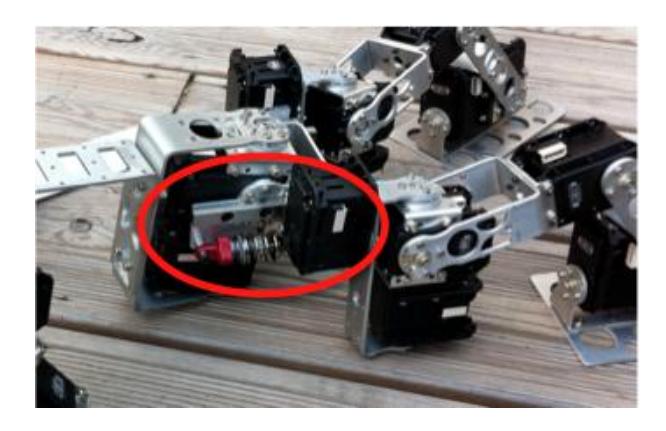
The mechanical structure of the robot involves 22 degrees of freedom: 6 for each leg, 2 for the pelvis (rotation in the sagittal plane and in the coronal plane), 3 for each arm, and 2 for the head (pitch and yaw rotations). The global shape of the robot is globally standard. However, as we already pointed out, our design focuses on the compliance of the structure. Our goal has been to improve the intrinsic stability of the system, and to avoid as much as possible inelastic shocks. Accordingly, we included several springs to the structure, as well as some flexible and soft materials like plastics and foam. We also introduced free linear joints controlled by dampers only. These joints absorb vertical shocks occurring during the gait, especially at the landing of the foot on the ground. These joints are located in the hips, allowing a vertical linear motion. Note that the design is still a work in progress, as we are searching for optimal uses of the semi-passive mechanical structure of the robot.
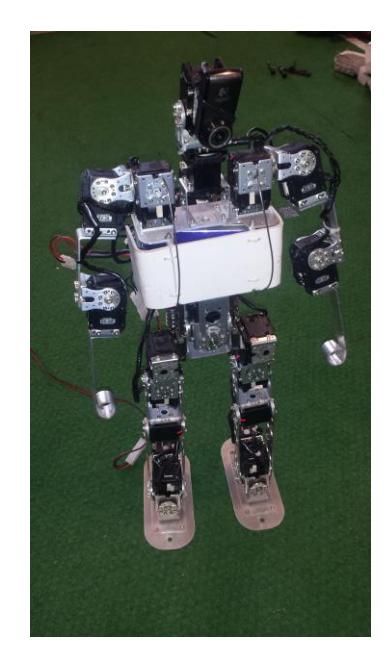
Main quantitative values describing the robot
| Value Unit | ||
|---|---|---|
| Degrees of freedom | 22 | |
| Weight | 4.0 | kg |
| Height | 56 | cm |
| Leg Length | 27 | cm |
| Arm Length | 27 | cm |
| Foot Length | 13 | cm |
Actuators and Sensors
All the joints are actuated by servomotors. We use off-the-shelf servomotors, that is, Dynamixel RX-24, Dynamixel RX-28 and Dynamixel RX-64 We also use Dynamixel servo position control (and feedback) in a standard way, but we exploit their maximum-torque control in order to again introduce compliance in the motions of the robot.
The robot gets feedbacks through the following sensors:
- Inertial Measurement Unit. We use a 9 degree of freedom IMU packaging a accelerometer, a gyroscopic and a magnetometer sensor providing both raws and orientation (yaw, pitch, roll) information through serial communication. The component is a Razor 9-Dof IMU.
- Camera. At the moment, the head of the robot is equipped with a Logitech webcam of type C905 on top of two (pan-tilt) servomotors. It samples pictures with a resolution of 640x480 pixels with a frequency of about 10 Hz.
– Joint Positions. On top of that, the robot uses also joint position feedback provided by each Dynamixel servo. In particular, considering some specific motion phases, one decreases the torque of some servo to make the motion compliant. Therefore, at these points, the joint position feedback becomes essential.
Processing Units
The embedded system is based on two main processing units: a small Cortex ARM7 microcontroller without operating system and a FitPC2i equipped with Linux (Debian 7). The FitPC has 2GB of RAM and is based on 1.6 GHz Intel Atom CPU while the ARM7 has 64kB RAM with 55 MIPS and run at 78MHz. More precisely:
The FitPC is in charge of the high-level behaviour management and the execution of the high-level programmed components:
- High-level decision processes. The behaviour of the robot is driven by state machines, mostly statecharts and finite state-machines (FSM).
- High-level motor primitive parametrization. The different movement of the robot are defined in terms of motor primitives. These motor primitives have high-level parameters used to adapt them in a continuous manner. These are the parameters through which the high-level system drives the robot.
- Motion scheduling. Communication with low level servomotors are clocked up to 50 Hz in Linux user space. Part of motions are defined by mean of splines.
- Elementary control unit. On top of splines, the motions are defined with several PID controller acting on different part of the robot, and also on some parameters of the motion (e.g., spline amplitude).
- Complex feedback analysis.
- Vision module.
- Communication with external entities (via WiFi IP protocol in development environment)
The ARM7 is in charge of the real-time low-level management:
- Sensors sampling and communication protocol.
- Servomotor control. The processing unit communicates with Dynamixel servos via a serial RS-485 bus.
We now describe in more details some of the above components, in particular the vision module, the localisation module and the motion control system.
Vision Module
The vision module of the Rhoban Football Club robot is responsible for making all the necessary image processing and analysis. This module runs on the Linux main embedded computer and it consists of a collection of programs and components written in C++.
Past years, our implementation was heavily based on OpenCV library (Open Source Computer Vision Library) [9,2]. This time, we focused our efforts on re implementing most of OpenCV low and high level algorithms we used in order to improve both control and performance of image processing. For example, re implementing an Hough line detector enables us to rafinate the filter of extracted lines segments and introduce useful a priori knowledge.
The vision module currently has the following characteristics:
- It essentially uses color images with the HSV color space.
- Objects detection use mainly color but also try to use various shape information through contour detection algorithms, Hough transforms, circle and ellipse fitting.
- An important preprocessing phase firstly extract the field from the image in order to reject the noisy unconstrained environment. Then, the ball and goal are separately looked for.
- Robustness of the detection/tracking processes has also been taken care of, in particular with respect to lighting and color variations, by using histogram transformations and distances.
We developed a graphical interface (coded in C#) for real-time forwarding and remote analysis of the output of the various vision algorithms.
Localisation Module
The localization module allows the robot to know approximately his position on the field. The estimation of the current position is used by the high-level state machine and can be used for taking decisions.
The localization relies on the analysis of the image to find the goal lines. This analysis is performed using color filtering and adaptive hough transform. When the analysis is successful, it outputs up to three lines (the two vertical and the horizontal sides of the goal) are these lines are then analyzed to extract the goal segments thanks to an adaptive analysis. The coordinates of the goal segments are then compared to a sample database, which is used to compute an approximation of the position and direction of the camera.
When one of the goals is in the field of vision of the robot then the localization process allows the robot to compute his position up to approximately 20cm.
High level behaviour take care to run the localisation module as frequently as needed to ensure that the robot position remains updated.
The graphical interface can be used to parametrize and monitor remotely the localization database as well as the whole localization process. Additional samples can be added dynamically to the database to improve the precision of the localization.
Motions
Behaviour Control
The motor behaviour of the robot is driven by two layers. The high-level behaviour is defined in terms of state machines. In turn, this state machines control low-level motor primitives. States define global behaviour, e.g. , "Searching the ball", "Tracking the ball", "Adjusting position for shooting", etc. There are two main state machines: One of them defines the behaviours of the head which is in charge of searching and tracking the ball. The second one defines the locomotion strategy. The state machines control motor primitives: they launch and stop them and they drive them via reduced sets of user-defined parameters.
Motion Design and Control
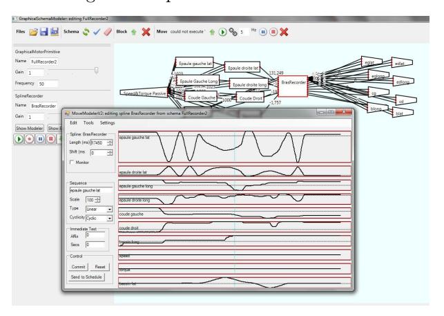
We design motions through a graphical framework environment we have developed where motions are subdivided into modules called parameterized motor primitives. Here is the general aspect of this environment:
Motor primitives are combined in order to form global motions of the robot in a modular way. Time is discretized; at each time, each active motor primitive computes relative output values; then, for each output, all these computed values are weighted and added to get the final output value. In turn, motor primitives are themselves organized in a classical way as block schemes involving inputs, basic blocks (filters) and outputs defined as follows:
– Inputs of the motor control system taken into consideration:
Sensors. At the moment, the robot is equipped with a 9 degree of freedom Inertia Measurement Unit.
Internal Motor Position. position error. When the motor is compliant, it makes an error in position regarding its position target. This position error can be measured accurately and is extensively used in the motor primitives. Motors can also return the load, i.e., the torque applied to the motor.
External Interfaces. Essentially during test phases, we use a joypad to control the parameters of certain motor primitive in real-time.
Splines. Inputs can also be splines, which are in our case piecewise linear functions defined by the user point by point. Let us note that seeing that the frequency of the motor control system is low, piecewise linear functions give already satisfying results.
Periodic functions. One can also use periodic functions (typically trigonometric functions) as input. This is used essentially to define Central Pattern Generator (CPG for short) as motor primitives.
– Outputs of the motor control system taken into consideration:
- Joint positions. This is the most basic output of the motor primitive system. It consists in fixing the target position of a particular joint.
- Joint maximal torque. This fixes a bound for the torque enforced by a particular servomotor.
- Operational space position of feet. Partial inverse kinematic is computed onboard by the platform: Cartesian position of each foot. This means that one can give orders concerning the Cartesian position of each foot.
- Motor Primitive Parameters. Some motor primitive parameters can be also used as output of the system. This means that a basic block can be used to modify for instance the amplitude of a particular spline. In a similar way, gains of outputs, of filters, speed of CPG can also be modified in this way.
The following classical types of blocks are available: proportional controller, weighted sum, mobile average, phase shift, discrete variation and integrator, PID, variation bounder.
In addition, one can define maximum and minimal bounds for each block input and output. Blocks can be combined with each other. For instance, this can be used to enforce PID controllers. Our method for motion design (including locomotion) is mostly empirical. We used the motion design environment to define motor primitives, exploiting sensors traces and motion tracking to get feedback.
Gait Design
Last year, our walking motion was primarily based upon CPG (Central Pattern Generator) system through our graphical tools. More precisely, the movement was generated by a collection of hand-made periodic signals and filtered by a set of interconnected filters (gain, delay, sum, bound on variation, ...). Reaction through sensors and servomotors feedback were thus aggregated to obtained a refined signal sent to joint low-level control layer.
This time, we are trying to come back to a classical spline and inverse kinematic feet control method with a slight but essential adjustment. One common pattern design with legs inverse kinematic is to craft a feet swing movement while ensuring that feet remain well parallel to the ground. We think this is not an efficient approach because extending the leg forward put lot of pressure on the inverse kinematic. To prevent the singularity, one have to bend the knee much more than a humanoid do, increasing the needed torque.
Instead, we are currently experimenting the feet leg position control in a more polar way. Legs inverse kinematic parameters are angle and radius of feet with respect to hip in place of Cartesian position. Thus, the walking step lies on a circle which seems to provide a more efficient and robust motion than our previous experiments.
Audio communication experiments
After experiencing unstable WiFi condition last year, we are currently experimenting a kind of sound based communication between robots. Information is transmitted as phase modulation in audio signal up to few bits per second. Our aim is to enable the robots to share some high level information during the game as strategy commands or ball and players localization positions. Many tests are still required to evaluate the potential of this communication medium to Robocup competition.
References
- Rhoban Robots at Yeosu International Expo 2012. http://www.rhoban-project.org/RobotsYeosu.html.
- G. Bradsky and A. Kaehler. Learning OpenCV: Computer Vision with the OpenCV Library. O'Reilly, 2008.
- The Rhoban Football Club. http://rhoban-system.fr/robocup2014, video: http://youtu.be/6d4HnOfJzxM.
- Gimbert H., Gondry L., Ly O., and Ph. Narbel. SigmaBan Team Description Paper. Humanoid KidSize League, Robocup 2011.
- O. Ly H. Gimbert, L. Gondry. SigmaBan Team Description Paper. Humanoid KidSize League, Robocup 2013.
- O. Ly, , M. Lapeyre, and P.-Y. Oudeyer. Bio-inspired vertebral column, compliance and semi-passive dynamics in a lightweight humanoid robot. In IEEE/RSJ International Conference on Intelligent Robots and Systems (IROS'2011), 2011.
- O. Ly and P.-Y. Oudeyer. Acroban the humanoid: Compliance for stabilization and human interaction. In IEEE/RSJ International Conference on Intelligent Robots and Systems, 2010.
- O. Ly and P.-Y. Oudeyer. Acroban the humanoid: Playful and compliant physical child-robot interaction. In ACM SIGGRAPH'2010 Emerging Technologies, Los Angeles, 2010.
- OpenCV Home Page. http://opencv.willowgarage.com/wiki/ (accessed, January 2011).
- Rhoban Project. http://rhoban-system.fr.