CIT Brains (Kid Size League)
Yasuo Hayashibara, Hideaki Minakata, Kiyoshi Irie, Naoaki Hatakeyama, Daiki Maekawa, George Tsukioka, Yasufumi Suzuki, Taiitiro Mashiko, Yusuke Ito, Ryu Yamamoto, Masayuki Ando, Yu Kato, Takanari Kida, Yuhdai Suzuki, Kazuyoshi Makisumi, Nung Duk Yun, Shouta Hirama, Yukari Suzuki, Chisato Kasebayashi, Akira Tanabe, Akira Kudo, Youta Seki, Moeno Masuda, Yuya Hirata, Yuuki Kanno, Tomotaka Suzuki, Joshua Supratman, Kosuke Machi, Shigechika Miki, Yoshitaka Nishizaki, Kenji Kanemasu, Hajime Sakamoto
Chiba Institute of Technology, 2-17-1 Tsudanuma, Narashino, Chiba, JAPAN; Sagawa Electronics, Inc., Matsudo, Chiba, JAPAN; Miki Seisakusyo Co, Ltd., 1-7-28 Ohno, Nishiyodogawa, Osaka, JAPAN; Nishizaki Co, Ltd., 1-7-27 Ohno, Nishiyodogawa, Osaka, JAPAN; Yosinori Industry,Ltd., 1-1-7 Fukumachi, Nishiyodogawa, Osaka, JAPAN; Hajime Research Institute, Ltd., 1-7-28 Ohno, Nishiyodogawa, Osaka, JAPAN
Abstract In this paper, we describe the system design by our Team, CIT Brains, for the RoboCup soccer kid size humanoid league. We have been participating in the Humanoid League for nine years. Three years ago, we redesign the system in which we put a large weight on maintainability and usability. In RoboCup 2014, we received first prizes on 4on4 soccer and technical challenge. Consequently, we were also awarded the Louis Vuitton Humanoid Cup. The system we developed has high mobility, high speed, strong kicks, well-designed control system, position estimation by a monocular camera and user-friendly interface. The robot can walk speedily and robustly. It includes feedback system with a gyro sensor to prevent falling. It also detects the positions of landmarks by color-based image processing. A particle filter is employed to localize the robot in the soccer field fusing motion model and landmark observation.
Keywords: Humanoid Robots, Programming Environment, Education Robotics
1 Introduction
In this paper, we describe our system for the RoboCup soccer kid size humanoid league. In 2014, we received first prizes on 4on4 soccer and technical challenge. Consequently, we were also awarded the Louis Vuitton Humanoid Cup in RoboCup2014 Brazil.
CIT Brains is a joint team consisting of Hajime Research Institute and Chiba Institute of Technology (CIT). Hajime Research Institute developed the mechanism and the prototype of control system of the robot. CIT developed computer system and overall intelligence such as perception and planning. CIT also made some contributions to improve the mechanism and control. We would like to emphasize that most of the members from CIT are undergraduate students. Any students who want to join this development can join the team. Senior students teach them from the basic knowledge of the robot system. We also aim to make an educational and research platform of intelligent humanoid.
2 Overview of the System
A photograph of our robot is shown in Fig. 1. The specification of the robot is indicated in Table 1. An overview of the system is shown in Fig. 2. Figure 3 shows the architecture of the software system. Our robot system consists of a USB camera, a computer board, an Inertial Measurement Unit (IMU), 17 servo motors, a battery and several user interfaces such as switches. Images are captured by the USB camera and processed on the main CPU board. The robot continuously estimates self-position. Depending on the data received, the robot selects its next behavior. Simple behaviors, such as moving, to complex behavior, such as following the ball, are described in the soccer strategy program. Commands to choose behaviors are sent to the body control process which decodes and execute the command. Each servo motors are daisychained; the commands are sent to all the motors which decodes and execute the commands. In total, this system is constructed as a well-designed hierarchic system. Therefore, the system can be modified easily.
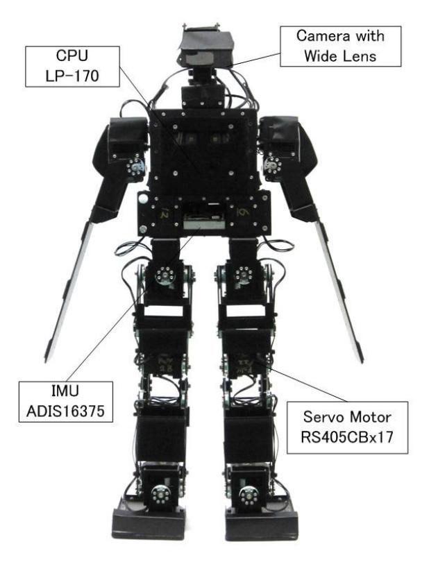
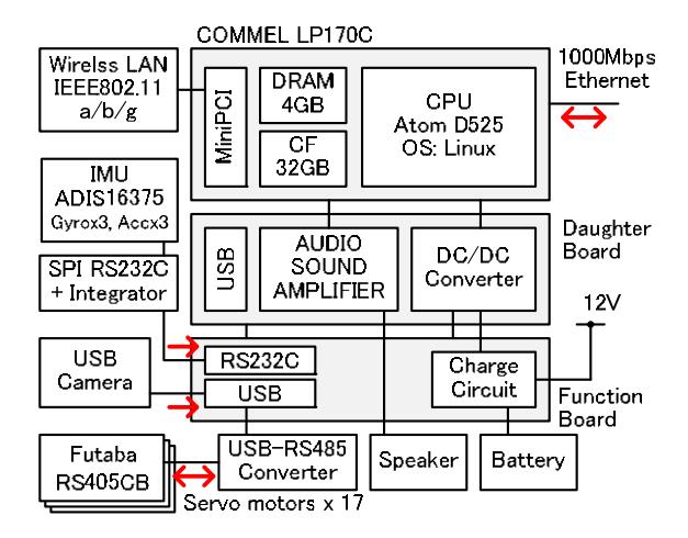
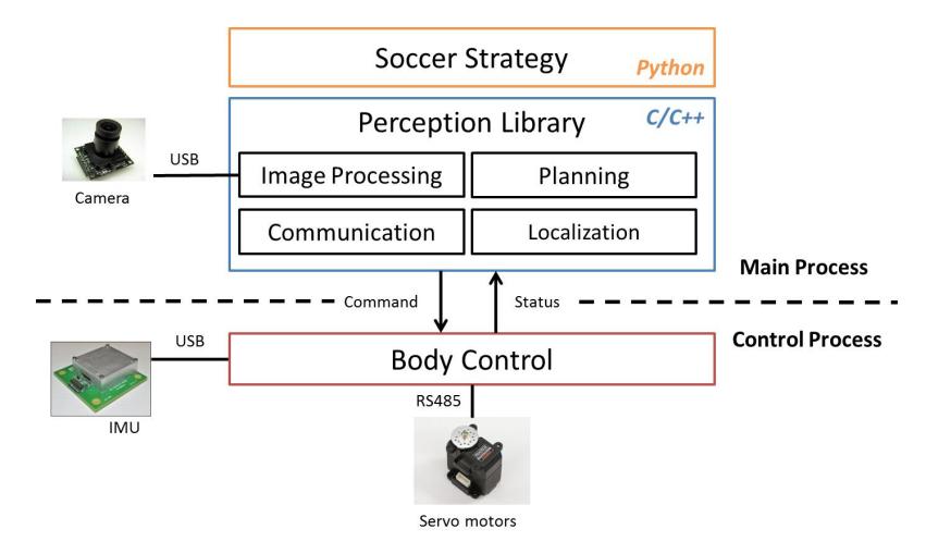
Table 1. Specification of the robot
| Weight | 3.5 kg (Including Batteries) |
|---|---|
| Height | 600 mm |
| Velocity (Forward) | 0.4 m/s (maximum) |
| Walking Directions | All Direction and Rotation |
| (Select the Angle, Stride, Period and so on) | |
| CPU Board | COMMEL LP-170C (Intel Atom D525 1.8GHz) |
| OS | Linux (Ubuntu12.04LTS) |
| Interface | Ethernet x 1, USB x 1, |
| Speaker, DIP switch x4, Push switch x 1 | |
| Servo Motor | Futaba RS405CB x 17 |
| Battery | 3S (11.1V, 5000mAh ) |
3 Mobility
One of the significant features of our robot is high-speed and stable mobility. When carefully tuned, the maximum walking speed is approximately 0.4m/s. It is important to keep the stability for long periods of time as many robots participating in the Humanoid League tend to become unstable in the later part of the matches due to overheating. Our robots, however, can maintain stable walk during full match.
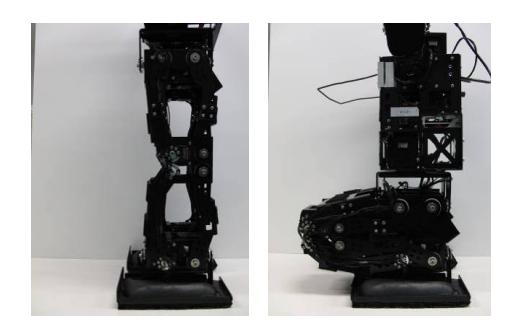
The leg structure is designed using a parallel mechanism as shown in the Fig. 4. The mechanism enables stable walking as the feet are mechanically kept angle to the body even if the motor has not synchronized completely while walking. Large torque servo motors are needed to prevent overheating. We employ Futaba RS405CB with a maximum torque of 48kg-cm. Active cooling fans are also attached to motors on the knees and the ankle joints. Heat from the motors is suppressed by abovementioned factors, and therefore our robot can walk stably even after long operations.
4 Computer System
This section describes the computer hardware and development environment.
4.1 Hardware
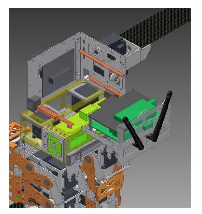
One significant feature of the robot is the high computational capability and the ease of maintenance. The computer board we employ (LP-170C) has an Atom D525 CPU, with a Linux operating system. Linux has advantages in ease of installation and operation compared to other operating systems we have previously used (Windows and NetBSD). All software modules we develop including perception and control are executed on it. To improve the maintainability of electronic components, we designed a slot-in mechanism for the main control circuit as shown in Fig. 5. From this mechanism, we eliminated a huge number of cables. Another nice feature is battery charging. Using an A/C adapter, batteries can be charged without using an external charger.
4.2 Development Environment
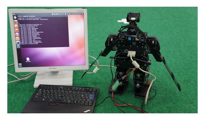
We have decided to install our development environment to each robot so that we can edit and compile source codes in the onboard computer. We directly operate the onboard computer by connecting a display and a USB keyboard (Figure 6), or remotely operate it via VNC. The charging circuit significantly improved ease of development. While we are editing and compiling source codes, we plug the A/C adapter to the robot and charge the battery. Servo motors are automatically powered off when A/C adapter is plugged. When we want to check the software using the robot, we unplug the adapter then the power of the motors is automatically turned on and we only need to put the robot on the field. We achieved laptop-like usability.
5 Software System
This section describes the software architecture and its components.
5.1 Architecture
Figure 3 shows the architecture of the software system. All software modules including perception, planning, and control are executed on the main computer board. Two processes are executed on a single computer: one is for perception and planning and the other is for control. Images are captured by the USB camera, and processed on the computer board to detect the position of the ball, other robots and landmarks. The robot continuously estimates self-position using the obtained information. Higher level of the robot behaviors such as following a ball are described in the soccer strategy programs. The soccer strategy programs are written in Python for ease of trialand-error type of development while the rest of the software modules are written in C and C++.
The body control tasks are operated in the dedicated control process. The control process controls the body according to commands sent from the main process such as walk and kick. The status of the robot (e.g. posture) is periodically sent to the main process. The control process operates the servo motors by sending commands to them. An IMU is used for gyro feedback and posture estimation.
We employ Internet Communication Engine (ICE) for communication between software components. ICE is a middleware for distributed computing including Remote Procedure Call (RPC). ICE is known to be computationally efficient compared to other middleware such as CORBA. Our software modules running in different processes or computer hosts communicate via ICE.
5.2 Image Processing
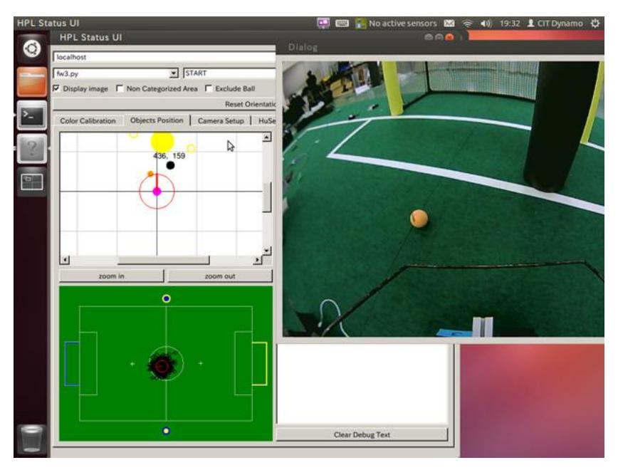
Objects such as balls or robots are detected by color-based image processing. Object colors are detected by a pre-calibrated look-up table. Regions of the same color are then grouped by a connected-component labeling algorithm. Object positions are calculated from the object position in an image and the pose of the camera under the assumption that all objects are on the floor. The pose of the camera is calculated by inverse kinematics. The resolution of the images can be selected from either 640x480 or 320x240. Our algorithm runs at 20 fps with onboard computer. An example of the calculation is shown in the Fig. 7. The color look-up table must be manually calibrated every time. We developed a GUI to build the table smoothly. The operator registers colors in images by clicking the image on the GUI. The color detection result is also displayed and updated real-time; therefore the operator can interactively calibrate and verify the color table.
5.3 Localization
The robot position and orientation are estimated using a particle filter that fuses motion estimations and observations. The hypotheses of robot position are represented by particles and they are updated as robot moves. The robot motion is estimated by kinematics and gyro. When landmarks such as white lines and goal posts are observed, the particles are weighted according to the observation likelihood and resampled.
5.4 Obstacle Avoidance
We use graph-based path planning for obstacle avoidance. Several control points are placed around the detected obstacles (i.e. other robots) and a complete graph is built by connecting all control points, start point, and destination point. Costs are set to all edges of the graph according to its length and distance to the obstacles. Dijkstra algorithm is employed to find the path with minimal cost.
5.5 Tools for Software Development
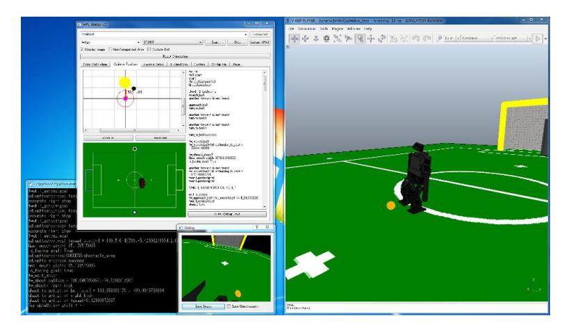
We developed a user-friendly GUI tool for soccer strategy development environment (Figure 8). The programmer can interactively check many kinds of things in this interface. The functionalities provided by the interface are as follows.
[User operation]
- Send commands to the control process
- Build a color look-up table
- Execute strategy programs by its name
[Status monitoring]
- Image data (both raw and processed image)
- Detected objects and their position
- Estimated robot position and particles
- Debugging messages
- Battery voltage and temperatures of servo motors
The GUI displays most of the significant status of the robot so that the programmer can check the algorism and find problems easily.
We also developed a simulator based on V-REP. V-REP is an open source robot simulator made by COPPELIA ROBOTICS. Almost all behaviors of robot such as motions and soccer strategies can be verified in this simulator. We can apply the verified code to the real robot without modification.
6 Conclusion
In this paper we describe our autonomous soccer humanoid system. Our system has high mobility, well-designed control system, position estimation by one camera, user-friendly interface and simulator.