Rhoban Football Club Team – Description Paper Humanoid KidSize League, Robocup 2015 Hefei
R. Fabre, H. Gimbert, L. Gondry, L. Hofer, O. Ly, S. N'Guyen, G. Passault, Q. Rouxel
CNRS, LaBRI, University of Bordeaux 1 33405 Talence, FRANCE
http://rhoban.com/robocup2015 · http://www.rhoban-project.org/RobotsYeosu.html · http://rhoban.com/robocup2014 · http://youtu.be/6d4HnOfJzxM · http://opencv.willowgarage.com/wiki/ · http://rhoban.com
Abstract This paper gives a short overview of the design of the kid-size humanoid robot Sigmaban of the French Rhoban Football Club Robocup team. The robot is built to play soccer in an autonomous way. It describes the main hardware and software components in their current state, major upgrades and research tracks for the upcoming Robocup 2015 competition.
1 Introduction
Rhoban Football Club1 is an on-going robotic project whose team members are researchers and PhD students at Bordeaux 1 University and CNRS. This project stems from the desire to better understand the problems arising from building a fully autonomous biped capable of human-like motions, and to thoroughly study the solutions of these problems from an empirical and a theoretical point-of-view. In this context, several prototypes have been already built and tested [7,8,10,6], focussing on walking, locomotion, interactions, and proposing some new solutions in terms of robot mechanical structure (e.g. spine-oriented) and compliance. The idea of playing a dynamic game like soccer – a very interesting testbed for producing complex situations in a constrained environment – has driven the team to design a robot with an improved structure, including video/image analysis and planning behaviour tactics, a necessary step forward to make the robot gain autonomy. Let us note that these robots have been showed in the French pavilion of the Yeosu International Expo 2012, in Korea (see [1]).
Our participation to Robocup 2015, up to the qualification procedure, would be the fourth one. The first one has been under the team name SigmaBan Football Club ([4]) while the second one at Robocup 2013 under current name Rhoban Football Club ([5]). For the first time, the team was able to submit three robust humanoid robots without major hardware problem. Finally, last year we took a big step forward by reaching the quarter-final.
1 formerly called SigmaBan Football Club at Robocup 2011, the page of the team is accessible at url:
http://rhoban.com/robocup2015 ([3])
For this upcoming year, our expectation is to focus on optimizing both vision and localization modules, meeting new color constraints and improving the walk control.
This short paper gives an overview of the Sigmaban robot hardware and software system in its current state with an emphasis on recent upgrades with the aim to participate to Robocup 2015 in Hefei.
Commitment
The Rhoban Football Club commits to participate in RoboCup 2015 in Hefei (China) and to provide a referee knowledgeable of the rules of the Humanoid League.
2 Hardware Overview
(This section contains subsections below)
2.1 Mechanical Structure
Since last year (2014) the mechanical structure of the robot has been reworked in a more classic design using 20 degrees of freedom: 6 for each leg, 3 for each arm, and 2 for the head (pitch and yaw rotations). The global shape of the robot is mainly standard. Compare to Sigmaban 1.2, Sigmaban 1.32 has been lightened by removing the linear dampers in the hip and the two extra degrees of freedom located above in the pelvis (rotation in the sagittal plane and in the coronal plane). This mechanical revision is a convergence to the classic Robocup Kid Size design but enables us to reach a more competitive locomotion. The space saved in the trunk allows for better electronics integration and thus a better mass distribution.
2 see the robot specification paper
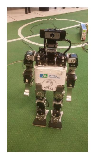
Main quantitative values describing the robot
| Value Unit | ||
|---|---|---|
| Degrees of freedom | 20 | |
| Weight | 3.8 | kg |
| Height | 54 | cm |
| Leg Length | 26 | cm |
| Arm Length | 24.5 | cm |
| Foot Length | 12 | cm |
2.2 Actuators and Sensors
All the joints are actuated by servomotors. We use off-the-shelf servomotors, that is, Dynamixel RX-28 and Dynamixel RX-64 We also use Dynamixel servo position control (and feedback) in a standard way, but we exploit their maximumtorque control in order to again introduce compliance in the motions of the robot.
The robot gets feedbacks through the following sensors:
- Inertial Measurement Unit. We use a 9 degree of freedom IMU packaging a accelerometer, a gyroscopic and a magnetometer sensor providing both raws and orientation (yaw, pitch, roll) information through serial communication. The component is a Razor 9-Dof IMU.
- Camera. The head of the robot is equipped with a Logitech webcam of type C930 on top of two (pan-tilt) servomotors. It samples pictures with a resolution of 800x448 pixels with a frequency of about 15 Hz.
– Joint Positions. On top of that, the robot uses also joint position feedback provided by each Dynamixel servo. In particular, considering some specific motion phases, one decreases the torque of some servo to make the motion compliant. Therefore, at these points, the joint position feedback becomes essential.
2.3 Processing Units
The embedded system is based on two main processing units: a small Cortex ARM7 microcontroller without operating system and a FitPC2i equipped with Linux (Debian 7). The FitPC has 2GB of RAM and is based on 1.6 GHz Intel Atom CPU while the ARM7 has 64kB RAM with 55 MIPS and run at 78MHz. More precisely:
The FitPC is in charge of the high-level behaviour management and the execution of the high-level programmed components:
- High-level decision processes. The behaviour of the robot is driven by state machines, mostly statecharts and finite state-machines (FSM).
- High-level behaviours. The different behaviours of the robot are implemented first in terms of simple raw C++ classes and then with a custom tool of flow graph visual programming.
- Walk motion generation. The walk generator is spline and inverse-kinematic based. It provides forward, lateral and rotation velocities high level parameters control.
- Motion scheduling. Communication with low level servomotors are clocked up to 50 Hz in Linux user space.
- Vision and localization module up to 15Hz..
- Communication with external entities (via WiFi IP protocol in development environment)
The ARM7 is in charge of the real-time low-level management:
- Sensors sampling and communication protocol.
- Servomotor control. The processing unit communicates with Dynamixel servos via a serial RS-485 bus.
We now describe in more details some of the above components, in particular the vision module, the localisation module and the motion control system.
3 Vision Module
The vision module of the Rhoban Football Club robot is responsible for making all the necessary image processing and analysis. This module runs on the Linux main embedded computer and it consists of a collection of programs and components written in C++ and based on OpenCV library (Open Source Computer Vision Library) [9,2].
This year, we focused our efforts first on reducing the whole computation time from image capture to ball and goal position detection. The time lag due to vision capture and processing is an important source of issues for both matching the real pan/tilt state at the capture time and ball approach control. The whole vision processing frequency have been optimized and raised from 5Hz to 15Hz. Work is also ongoing to meet the new colors constraints of this year. Both ball and goal detectors are being rewrite for white color.
Our global strategy is to loose the requirement of non false positives for features detectors in order to simplify the processing and instead rely on the particle filter to select out the likely ones.
The vision module currently has the following characteristics:
- It essentially uses the raw camera YUV color space.
- An important preprocessing phase firstly extract the field from the image in order to reject the noisy unconstrained environment. Then, the ball and goal are separately looked for.
- Ball detection looks for ball candidates and score them accordingly with their apparent radius, distance and a measure of circularness of shape.
- Goal detector is mainly looking for the goal post bases because they remain in the field green and are easier to extract than upper unconstrained background.
4 Localisation Module and particles filter
(This section header is present in the original paper but contains no content)
5 Motions
(This section contains subsections below)
5.1 Behaviour Control
The global behaviour of the robot is driven by two layers. The high-level strategy is defined in terms of state machines. In turn, this state machines controls the scheduling of simple flow graph based behaviours. States define global behaviour, e.g. , "Searching the ball", "Tracking the ball", "Walking to the ball", etc. There are two main state machines: One of them defines the behaviours of the head which is in charge of searching and tracking the ball. The second one defines the locomotion strategy.
5.2 Motion Design and Control
We design behaviours through a graphical framework environment we have developed where tasks are subdivided into modules or scenes scheduled in parallel. Here is the general aspect of this environment:
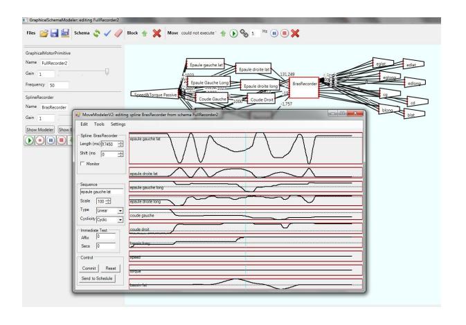
Inputs of the motor control system taken into consideration
- Sensors. At the moment, the robot is equipped with a 9 degree of freedom Inertia Measurement Unit.
- External Interfaces. Essentially during test phases, we use a joypad to control the parameters of certain motor primitive in real-time.
- Splines. Inputs can also be splines, which are in our case piecewise linear functions defined by the user point by point. Let us note that seeing that the frequency of the motor control system is low, piecewise linear functions give already satisfying results. This is use essentially for standing front and back motor primitives.
- Periodic functions. One can also use periodic functions (typically trigonometric functions) as input. This is used essentially to define Central Pattern Generator (CPG for short) as motor primitives.
Outputs of the motor control system taken into consideration
- Joint positions. This is the most basic output of the motor primitive system. It consists in fixing the target position of a particular joint.
- Joint maximal torque. This fixes a bound for the torque enforced by a particular servomotor.
- Operational space position of feet. Partial inverse kinematic is computed onboard by the platform: Cartesian position of each foot. This means that one can give orders concerning the Cartesian position of each foot.
The following classical types of blocks are available: proportional controller, weighted sum, mobile average, phase shift, discrete variation and integrator, PID, variation bounder.
5.3 Gait Design
The walk motor primitive is mainly open-loop, based on splines and classic inverse kinematic of legs. Three periodic functions defined as three polynomial cubic splines and made of very few points are used as base for rise, step foot and lateral oscillation movements. Theses spline normalized signals are then sent to the inverse kinematic X,Y,Z input after some offset, gain and phase shift. Angular motor reference positions are then computed for each leg. Some motors as hip yaw (legs rotation) ans arms are also directly control without inverse kinematic.
The whole walk generator can be summarised as a directed acyclic signal flow network with spline signals as inputs, inverse kinematic block for each leg in the middle, motor position references as outputs and various offsets, gains and phase shifts signal filtering. This design leads to a set of open parameters divided in two categories. First, there is about 10 "static" parameters such as movement frequency, foot height rise, amplitude of lateral oscillations, etc.. which are not update during the movement and have to be tunned manually. The 3 other parameters are "dynamic" and used to control the walk (forward, lateral step length and turn gain oscillations) from the high level.
5.4 Optimization and Learning
The walk generator has always had many open parameters which were mainly tunned by hand for our last participations to Robocup competition. Since this is an expert and time consuming task, one ongoing track is to try classic and state of the art gradient and EM based methods for automatic optimization of such parameters. We are currently working on an experimental setup where the humanoid robot is tracked and controlled (forward, lateral position and orientation) by a motion capture system to remain walking on a slow treadmill. Long stable walk sequences are achieve. We are trying to examine the effectiveness for Robocup application of this setup for walk motion optimization with respect to some stability and energy consumption fitness criterion.
6 A new open-source servomotor firmware
This year, we created an open-source firmware for the MX64 servomotor. Our goal is to get full control over the low-level layer of our robot to make it better. We chose the MX64 for its current sensing capabilities (which allows torque control). A custom firmware opens up for a lot of possibilities, such as non-PID control loops, communication protocol optimization and power consumption enhancement. We are currently working on a predictive feedback control approach and a trajectory management. Ideally, instead of sending position orders to every servomotor we would like to send them a trajectory, thus achieving an improved dynamical precision.
References
- Rhoban Robots at Yeosu International Expo 2012. http://www.rhoban-project.org/RobotsYeosu.html.
- G. Bradsky and A. Kaehler. Learning OpenCV: Computer Vision with the OpenCV Library. O'Reilly, 2008.
- The Rhoban Football Club. http://rhoban.com/robocup2014, video: http://youtu.be/6d4HnOfJzxM.
- Gimbert H., Gondry L., Ly O., and Ph. Narbel. SigmaBan Team Description Paper. Humanoid KidSize League, Robocup 2011.
- O. Ly H. Gimbert, L. Gondry. SigmaBan Team Description Paper. Humanoid KidSize League, Robocup 2013.
- O. Ly, , M. Lapeyre, and P.-Y. Oudeyer. Bio-inspired vertebral column, compliance and semi-passive dynamics in a lightweight humanoid robot. In IEEE/RSJ International Conference on Intelligent Robots and Systems (IROS'2011), 2011.
- O. Ly and P.-Y. Oudeyer. Acroban the humanoid: Compliance for stabilization and human interaction. In IEEE/RSJ International Conference on Intelligent Robots and Systems, 2010.
- O. Ly and P.-Y. Oudeyer. Acroban the humanoid: Playful and compliant physical child-robot interaction. In ACM SIGGRAPH'2010 Emerging Technologies, Los Angeles, 2010.
- OpenCV Home Page. http://opencv.willowgarage.com/wiki/ (accessed, January 2011).
- Rhoban Project. http://rhoban.com.