Team RoBIU
Golman Roman, Elkaras Avraham, Siri Gilad, Yaakov Avia, Schreiber Elimelech, Waserman Yoni, Spokoini Noam, Druker Itai, Zuckerman Michael, Amsalem Rafi, Abramov Benjamin, Kolberg Eli
Bar-Ilan University, Faculty of Engineering, 52900 Ramat-Gan, Israel
https://github.com/BIU2015/RoboCUP2015/wiki
Abstract Team RoBIU was founded in 2010, the team consists of undergraduate students from Bar-Ilan University Faculty of Engineering. This paper presents an overview description of the hardware and software layer of the kidsize humanoid robots of RoBIU team. The paper describes the robot's hardware specifications and a high level description of the various software algorithms, including real-time image processing, stabilization, sensors and camera based localization, debug features, robot agents inter-communication and high-level behaviors implementation.
1 Introduction
This paper describes the Robocup Kid Size League team RoBIU from Bar Ilan university. The team was founded in 2010 and this is the 4th year in a row the team is participating the KSL league. Each year the team is assembled with new undergraduate senior computer engineering students, as a part of their final year project under the supervision of Mr. Rafi Amsalem, Mr. Beni Abramov and Dr. Eli Kolberg. The purpose of the Robocup KSL project is (beside the obvious: academic research) partially, to expose students to a large-scale project and allow them to gather experience in handling multiple challenges, such as strategics orientation, coping with deadlines, mediating between target groups and managing the development of software-intensive systems.
RoboCup 2015 would be a great setting to study our enhanced software and team performance.
2 Commitment
The RoBIU team hereby commits to participate in the Robocup 2015 Kid Size League Humanoid competition taking place in Hefaei, China.
The RoBIU team will provide, upon demand, a person with sufficient knowledge of the rules to referee during the competition.
3 Robot Specifications and Hardeware
Robot Specifications, Hardeware, and Sensores are discussed seperately in the Robot Spcifications document.
4 Software
Our robots are composed of several modules, combined to create a real time robot soccer player. The software controlling the robots is designed to handle several tasks simultaneously, so multithreading is essential. The multithreaded environment allows the delegation of the robot's authorities (such as State machine, Vision, Localization etc.) in order to increase efficiency. By using a multithreaded environment we can use the same memory space for all threads, and inter-thread communication is faster. The Multi-core i5 processor increases the gain achieved by multithreading even more, by running the threads on seperate cores.
4.1 Artificial Intelligence
Artificial intelligence AKA Brain - is the main process of the robot. It's in charge of processing all important inputs from other modules, and form a decision as to the next move, or state. We started by writing a simple Brain which knows how to find the ball and kick to the opponent's goal. Then slowly incorporating additional factors such as Localization properties, inter-robot communication, and advanced behavior algorithms, ended up with quite a sophisticated AI program.
4.2 Vision
We use the HSV image format[1]. Image description in terms of it's RGB color components make object discrimination difficult, as RGB color components are correlated with the amount of light hitting the object, and therefore with each other[2]. Practicaly, what we humans percieve as a certain color, is hard to specify distinctively in terms of RGB. Instead, HSV color description (hue/saturation/value) is far more relevant, as the color and intensity fields are described separately and independently. This color representation is achieved by a non-linear transform from the RGB, and implemented using some functions from the OpenCV library[3]. We start our image processing with an image segmentation. This is done in a very simple way, using the thresholding method.
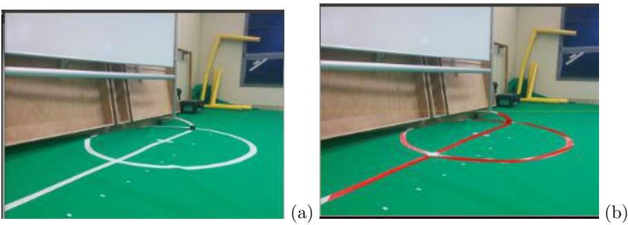
We developed unique Vission algorithms to deal with various tasks: histogram normalizer, noise reduction, line&corner detection and classification, and more.
Each object is detected not only by color, but by shape detection algorithms as well. By combining the two features we increase object detection and classification significantly. For instance:
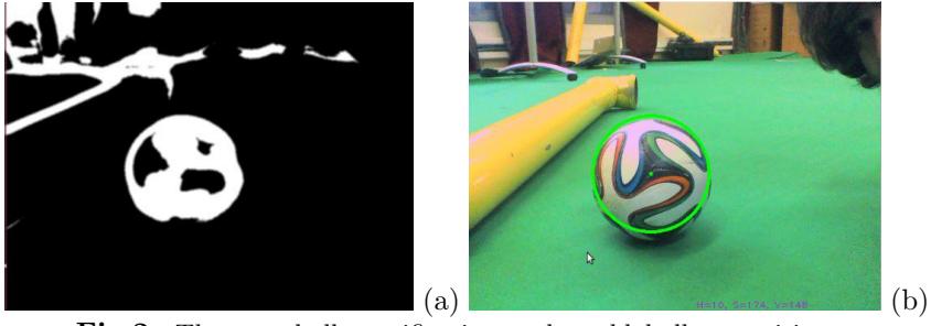
Ball recognition using Hough transform. This year, since the ball is not uniformly colored, we cannot solely rely on colors to find the ball. So we decided to use OpenCV function HoughCircles that "Finds circles in a grayscale image using the Hough transform" [4]. We are also using the fact that we know the balls colors, trying to combine them to a whole circle shape. Another feature we implemented is OnGreen check of the supposed ball, to determine if the detected circle is above the green field or not. Allowing us to Rule out alien objects (the crowd for example).
Automatic color calibration. In order to use the thresholding method, we need to know one little thing: What are the HSV threshold's for different colors? Of course we can check them in Wikipedia, but this will not work because colors differ from place to place due to light, object surface, camera, etc. So we needed a dynamic way to determine the thresholds. To achieve this we made a program that shows to the user the current stream from the camera, the user selects color to set and clicks on an object of this color. The program saves the HSV values of the selected point, and the surrounding pixels- to determine HSV range of the selected color. Thus allowing the robot to learn the needed threshold's at every new location.
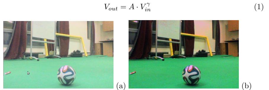
Blind Gamma filter. Even in the same room the lighting and shading of objects can may vary drasticaly, rendering color dependent and lighting sensitive algorithms unpredictable. In attempt to Deal with such effects we implemented Automatic Gamma correction filter that compensates for lighting variations adjusting and normalizing image brightness, using power-law expression:
The main problem of this method is how to automatically determine the correct gamma for the transformation.There are several scientific papers that attend to this problem, but most of the solutions involve computation complexity inadequate for real time purposes, so we are working on a real time blind gamma correction algorithm.
We also use Gaussian Blur Filter to clean noises before preforming vision calculations and transformations. It helps the HoughCircles for example, to avoid false detections.
All information retrieved from the object detection is passed on to the Localization thread, described later.
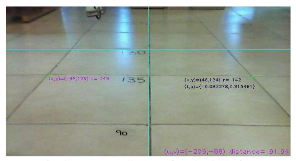
Distance. The identification and classification of an object from image input data is much more useful if the distance to this object can be approximated. We've developed, tested, and are currently fine-tuning a method of measuring object distance from monocular camera input. The method is based on the Pinhole Camera Model, and takes into consideration known camera parameters, variables, and other characteristics of the problem. Once an object is detected, the distance and angle to it are calculated from the image data.
We have come up with the following transform equations, which transform pixel values from u,v image plane, to the real world x,y plane, the field of game in front of our robot:
$$y = Height \cdot tan(\phi + atan(v/f_y)) \tag{2}$$
$$x = \left(u \cdot Height/f_x\right) \cdot \frac{\left(tan(\phi) \cdot \left(tan(\phi + atan(v/f_y)) - tan(\phi) + 1\right)}{(1 + tan(\phi)^2)^{1/2}}$$ (3)
$$x = Height \cdot tan(\phi + atan(v/f_y))) \cdot u/f_x \tag{4}$$
Where : Height- is height of camera from plane. fx, fy- are effective focus distances of camera lens in the horizontal and vertical direction respectively. φis the angle of camera taken from the vertical axis. Eqn.3 is taken for low φ values, and eqn.4 for greater φ values, as some terms in eqn.3 become negligible or irrelevant.
The angle from each object can be easily calculated from the above x,y real plane values, but sometimes are preferably calculated by the formula:
$$\alpha_{deg} = (Object\ Offset){pxl} \cdot \frac{Horizontal\ Angle\ of\ View{deg}}{Frame\ Width_{pxl}} + Head\ Pan_{deg}\ (5)$$
where the fraction in the above formula is a constant, which depends on the camera properties.
An article on the subject of Distance by Look-up-table Method, a different method developed by last-year-team-member Michael Zukerman, is soon to be published.
4.3 Localization
Localization is the logical approximation of the robots position and orientation in the playing field space, based on previous knowledge of the field (eg. the location of goal posts, white lines and exact field dimensions), knowledge of the dynamic entities on the field (eg. goalie, other robot players and robots own previous location), and inputs from the robot's built in sensors (eg. camera, foot pressure sensors, gyroscopes magnetometers and accelerometers.).
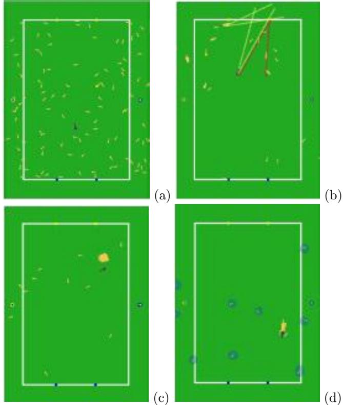
Localization was implemented by means of what is known as Particle Filter, which is, simply put: Iteratively calculating the likelyhood of many random localization possible states, ultimately convreging to the true state. This year we intend to incorporate magnetometer sensor data (compass), hopfuly increasing stability and robustness of loaclization.
We intend to upgrade our current camera - a webcam quality camera, designed specifically for close proximity imaging of faces, with a higher resolution camera. Our experience has tought us that trying to identify thin lines at a distance, with our current imaging hardware, is tricky at best. However, given reliable inputs, after a number of iterations the particles converge to the actual robot location(fig. 5-c).
4.4 Motion and Stability
Motion contains walking behaviors and actions. Dynamixel MX-28 is the robot's servo. It lets us use high resolution (4096) engine state. We intend to use the last years achievements as a starting point, and apply improvements and modifications to solve existing problems, as well as new ones, as they present themselves (such as present-year's new chalenge: grass-walking). We will aplly forward kinematic calculation algorithms for control of robot motion and stability.
4.5 Communication
Our robots use a unique message format sent via UDP protocol for inter-robot comunication, developed last year by the previous team members. We might apply mild modifications as the need arises.
4.6 Debug and Game Control
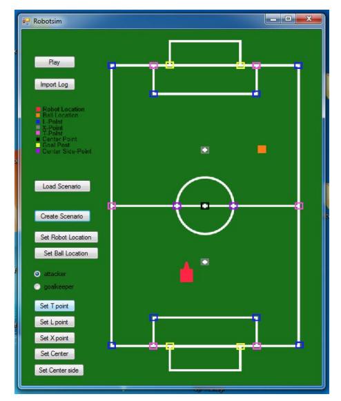
To improve our debugging capabilities (in case of crashes and other runtime errors) we implemented a Log class that is responsible for saving a log of every important step of our robot control program, so we can closely follow each step of our program and see what led to every situation the robot got into. We also made use of time.h class to be able to measure frame rate of our vision functions and the frequency of our state machine (which is also saved into the log). We have a real-time debugging console which listens to the robots reports and displays them on a special UI. The program will help us to understand the status and localization valuation of each robot, it will also allow the examination of decision-making processes of each robot.
5 Conclusion
In this paper we've introduced the mechanical structure and software design of our robot. Although it's the 4th year Bar Ilan University is competing, all team members have changed (except for the mentors), so this is our first time participating in the competition. We look forward to participate in the RoboCup competition this year, and are determined to play as worthy competitors.
References
[1] R. Gonzalez and R. Woods, Digital Image Processing, Third Edition, Pearson Education, 2008. [2] Wikipedia https://en.wikipedia.org/wiki/HSL and HSV. [3] G. Bradski and A. Kaehler, Learning OpenCV: Computer Vision with the OpenCV Library, O'Reilly Media, October, 2008. [4] http://homepages.inf.ed.ac.uk/rbf/HIPR2/hough.htm http://docs.opencv.org/modules/imgproc/doc/featuredetection.html?highlight = houghcircleshoughcircles