Berlin United - FUmanoids Team Description Paper for RoboCup 2016
Lutz Freitag, Jan Draegert, Simon Gene Gottlieb, Gregor Barth, Michael Pluhatsch, Arne Schmidt, Tanja Linkermann, Erik Sporns, Daniel Seifert, Raúl Rojas
Institut für Informatik, AG Intelligente Systeme und Robotik, Freie Universität Berlin, Arnimallee 7, 14195 Berlin, Germany
http://www.fumanoids.de · http://www.fumanoids.de/opensource · http://www.fumanoids.de/publications · http://www.fumanoids.de/code/framework · http://www.fumanoids.de/code/coderelease · http://www.fumanoids.de/code/hardware
Abstract This Team Description Paper describes the humanoid robot team Berlin United - FUmanoids and presents robots for participation in RoboCup 2016 in Leipzig, Germany. A general overview of the team and its history will be given as well as insight into research interests and particular areas of the robots' software and hardware.
1 Introduction
Berlin United - FUmanoids is a humanoid robot team participating in the Humanoid KidSize League at RoboCup. The team was founded in 2006 as the successor of the Mid- and SmallSize team FU-Fighters.
During the time of participation at RoboCup, the team had significant successes in competitions, achieving 2nd place in 2009 and 2010, 3rd place in 2007 (its debut competition), 4th place in 2011 and reaching the quarter finals in 2008, 2012, 2013 and 2015. In 2014 and 2015 the team scored 1st place in the RoboCup German Open competitions. At the Iran Open 2014 the FUmanoids scored 1st and 2015 2nd.
This paper presents the team's research interests, contributions to the Robo-Cup community as well as the hardware and software of the FUmanoid robots.
2 Research and Contribution
The main research interests are:
- dezentralized control architecture for humanoid robots
- image processing to reliably classify YUV-triples as logic colors even when light conditions change
- real-time capable vision and detection algorithms for soccer games
- fast and stable walking
- development of sophisticated hardware to perform low level diagnostics of the overall system
The team is committed to further the Humanoid League and the research exchange between teams. For this reason the team is one of few Humanoid League teams that releases their source code, schematics and designs for hardware components on a regular basis. The current software release (2015, [3]) consists of FUmanoid, the main program running on the robot, and FUremote, the control and debugging program based on Eclipse/RCP. Each release resembles the software and hardware used in the previous RoboCup championship. Additionally, the developed framework is also released ([2]). The custom built hardware is part of the release [4] as well as the software running on the microcontrollers. Theses and papers on the robots are available on our website.
3 Hardware
(Hardware overview)
3.1 Mechanical Structure
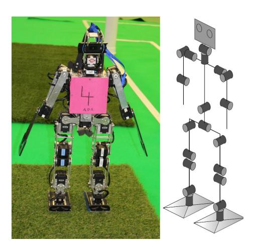
The current robot model was designed and constructed with respect to simplicity and both human-like proportions and capabilities. It features a parallel kinematic leg design, with an additional servo motor added to allow the torso to move laterally, imitating the human spine movement that keeps the torso upright. The total height is 65 cm.
For actuation, we use Dynamixel servo motors from Robotis Inc., namely RX-28 and RX-64 servos. They provide 20 degrees of freedom — 5 per leg, 2 for upper-body movement, 3 per arm and 2 in the head (Fig. 1). To remove jitter caused by worn-out potentiometers, we modified the servos to use a hall sensor (magnetic encoder) for reliable measurements of the current joint angle.
Due to last year's rules introducing artificial grass the FUmanoids designed a new robot platform based on the Minibot/Hulk platform of the Hamburg Bit-Bots. The new platform does not have any parallel kinematics; instead it utilizes the more common approach for the hips and legs - 3DOF in the hips, 1DOF in the knees and 2DOF in each foot. For actuation we use Dynamixel servo motors from Robotis Inc., namely MX-106, MX-64 and MX-28 – six per leg, three per arm and two in the head. For the body parts 2 mm aluminum is used with the advantage of growing from 65 cm to a total height of 76 cm with only slightly more weight and a lot more space inside the torso. The new generation will play in a mixed team with our old platform.
3.2 Sensors
We equipped the robot with the following sensors:
Actuators: The feedback of the actuators includes the current joint angle, motor speed and load.
IMU: The sensor board includes an integrated 9 axis IMU, featuring gyros, accelerometers and magnetometers. A Kalman filter provides filtered output that is used by the robot for stabilization as well as calculation of the camera perspective in order to obtain localization data.
Camera: The robot is equipped with a commercially available webcam (Logitech HD Pro Webcam C910). Using a resolution of 960x720 it delivers 30 frames per second using Motion JPEG.
Power Supply: A smart power supply permanently monitors the battery's voltage, the voltage on the servo motors and on the 5 V power domain (each with mV accuracy) that powers the main computer. Additionally the power supply measures the current consumed by the servo domain as well as by the 5 V domain (each with cA accuracy). Each of those measurements are performed on a 120 kHz basis to guarantee quick responses from the power supply.
3.3 Main Computing Unit
In order to satisfy increased performance requirements, we are using an ODROID-X2 board featuring an Exynos4412 Quad-core ARM Cortex-A9 CPU clocked at 1.7 GHz. It provides all necessary extension interfaces, such as multiple USB ports (for the camera and the WiFi module), Ethernet and a UART connection.
We utilize Linux as operating system, based on a custom-compiled kernel and the Linaro distribution.
3.4 Sensorboard
In order to improve communication speed and frequency with actuators and sensors, we developed our own sensor board. It supports connecting the actuators of each leg and the upper body separately in order to set and get servo positions on each bus in parallel. Two ARM Cortex M4 processors, clocked at 168 MHz each, handle both the Kalman filter, which is used by the IMU, and the efficient servo communication. Data and actions, e.g. movements of the robot, that are triggered via a dedicated serial connection, can be requested by the main unit.
4 Software
(Software overview)
4.1 Inverse Kinematics
Robots are actuated with servomotors which are either configured with target angles and velocities or torque. Setting the desired parameters in a "raw" fashion is very cumbersome when dynamic movements shall be performed. Inverse kinematics creates a different way of describing motions: Instead of manually calculating the target angles for a given pose we create tasks which represent some target configuration. An example: We want the robot's right hand - this is the task's end effector - to move to a specific point in the torso's reference coordinate frame - this is the task's base coordinate frame. The inverse kinematics calculates the angle changes in the motors necessary to accomplish the task.
Our inverse kinematics solver implements the ability to formulate multiple levels of tasks where higher-level tasks cannot be violated by tasks with lower priority. This is useful as some tasks are more important than others — e.g. balancing is more important than having the camera point towards a specific point. Less important tasks are solved within the combined-nullspace of all more important tasks. We also have implemented a technique to define the target solution space of tasks. That means our robots can solve the inverse kinematics problem for different task subspaces independently, thus greatly reducing overshooting at near-singular configurations.
4.2 Locomotion and Stability Control
The walking system of the FUmanoid team is based on dynamic trajectories that are designed to realize Zero Moment Point (ZMP) optimization. These motion patterns allow the robots to walk in every direction with speeds up to 25 cm/s. The walker is implemented with usage of the inverse kinematics solver shown in 4.1.
Walking is mostly defined from the perspective of the feet and involves the whole body dynamics. The tasks (in terms of inverse kinematics tasks) involve the movement of the feet with respect to each other and the movement of the center of mass (COM) with respect to the supporting foot. The lateral velocity of the COM is matched to either keep the linear momentum inside the support polygon or to accelerate towards the target position of the swing foot. As long as the tasks can be fulfilled this suffices the criteria of a ZMP based walker. Due to the utilization of the whole body dynamics even body parts which are not intuitively associated with the process of walking (e.g. arms) are used to manipulate the COM and its dynamics.
The walker is designed to be usable on other robot platforms as well since the static properties (e.g. where is the COM in the idle position; what is the geometry of the robot) are once calculated with the forward kinematics and used as parameters for trajectory generation. This leads to a highly reusable walking process which is highly customizable as well.
4.3 Computer Vision
The vision modules are grouped in independent layers:
- Color Analysis The color analysis is done on a high dimensional cluster classification base. Each cluster is built around sample color points which represent a logical color (green/field, white/goal, white/field lines, . . . ). A further description on the algorithm is given in 4.3.1
- Field Contour Analysis The field contour divides the image in two parts where the part above the field contour contains only information about objects outside the soccer pitch and can therefore be discarded. The lower part contains the visible areas of the pitch and is used for further image processing steps. The calculation of the field contour is based on vertical scan lines of green and white classified pixels.
- Object Extraction In the object extraction step all the relevant objects on the pitch are constructed out of their color-features. The currently provided objects are ball, goals, field line points and obstacles. The positions of goal poles in the image are extracted by sampling along the field contour and/or horizon. The ball detection is described in detail in 4.3.1.
4.3.1 Color Classification
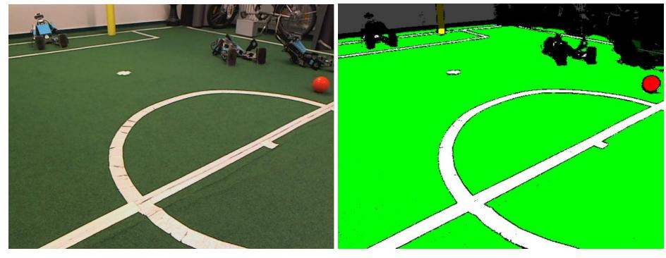
Every logical color is modeled as a Gaussian Mixture Model (GMM), meaning a weighted sum of Gaussian (Normal) distributions. This method has been known to describe the typical shades and variations of the colors quite well. The model also accounts for the case of multi-colored items like the new ball, since it will just fit separate Gaussian components to the different colors. The training of the parameters is done right before the game so the individual lighting and location conditions are considered. The samples needed for the training are created by identifying the objects to be classified in the camera image. To fit the model to the samples the Expectation-Maximization algorithm is used, which can be thought of as a kMeans clustering algorithm with variable covariance matrices. The exact number of Gaussian components is calculated automatically and individually for each logical color according to its complexity. A classification result can be seen in Fig. 2.
4.3.2 Object Extractors
As described in 4.3.1, logical colors are encoding objects in the game environment. The robot transforms each raw (YUV) camera image to a color classified image whose pixels encode the logical colors of each raw pixel. Notably each pixel can represent multiple logical colors at the same time using bit masks. Furthermore we calculate an integral image on the colorclassified image. The integral image's pixels contain an integer for each logical color with the amount of pixels of this color in the rectangle from the top left to the pixel's coordinates:
$$p_{integral}(x,y) = \sum_{i=0}^{x} \sum_{j=0}^{y} p_{color}(i,j)$$
with pintegral(x, y) as the pixel at x, y in the integral image and pcolor(i, j) as the pixel at i, j in the color-classified image.
With the integral image we can search efficiently for bounding boxes of blobs with a specific logical color. The search (shrink operation) is performed as a binary search for each parameter of the boundary box (left, right, top and bottom bound). Subsequently, the color coverage of the box is calculated. If it undercuts a threshold the shrink operation is repeated in each of the four quadrants of the shrunk bounding box. This is implemented recursively and yields a non-balanced binary tree representing the topology of the distribution of the specified color.
This procedure is used to detect the ball, goals, field lines and obstacles. Since last year's rule changes, the ball has mostly the same color as the field lines. We take this into account by testing each ball candidate — each leaf of the binary tree representing the logical color white — for specific "ball-like" features. To determine if a blob actually is a ball or not, our robots utilize a chain of classifiers that increase in complexity and accuracy. The chain starts by testing if the top half of the ball candidate is brighter than the bottom half, continues by testing the candidates' size, tests the logic-color distribution, matches against a known color distribution with the Kullback-Leibler-Divergency [5] and finally uses an SVD.
4.4 Modelling
(Modelling overview)
4.4.1 Object Modelling
In order to track the ball, obstacles and goals, we employ extended Kalman filters [6]. The ball model involves the position and velocity of the ball. The goals are modeled by four independent poles. This approach allows us to distinguish between the opponent's and our own goal. Obstacles are modeled by a dynamic number of Kalman filters. They also keep track of the team colors.
4.4.2 Teamball
A teamball is beneficial when a player does not know where the ball is located. In this situation well-informed team mates can supply him with estimations about the ball's position.
We designed the teamball model for several use cases: The goalie or the defending robots usually want to rotate towards the ball or position themselves between the ball and our own goal. Frequently, the ball is situated out of their detection range. The teamball enables an improved positioning in order to more likely block a strong shot or just to detect the ball sooner. A player that tries to approach the ball actively, such as the striker, does also benefit from a teamball model. When loosing the ball, it is advisable to move to the teamball position and to figure out if the ball is lying there.
To obtain valid information, all team mates that are localized and hold a ball model are consulted. If no team mate is localized, our workaround is to use the goal model instead. To pick the best ball position of several proposals, we exclude balls lying outside the pitch, and rate the remaining balls by the distance to the median position. Additionally, we take the relative ball positions of each team mate into account. Moreover, we assume that the goalie knows its position quite well, so its information is given additional weight.
We contrast the highest rated ball with the ball that gained the runnerup score. In the case that these scores are similar, but both positions are far away from each other, it is not reasonable to opt for any of these positions. Furthermore, we invalidate any teamball that is located in the visual range of the robot.
4.4.3 Motion Editor
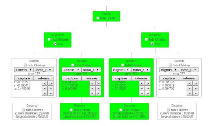
The FUmanoids utilise the general inverse kinematics solver in the motion editor (Fig. 3) to define motions. This enables movements to be created easily and effectively. The fundamental idea is to define tasks in a more abstract way in order to achieve robot independent motions. The goal is to run these tasks on different robots that not only differ in link size but also in number and type of joints. A task is mostly defined by two effectors and their position and orientation to each other. The inverse kinematics will compute which actuators are involved. It is possible to define multiple tasks that can be executed at the same time. Dependencies between the tasks are resolved by prioritization.
While the problem of executing tasks in parallel can be resolved this way, the issue of sequential tasks remains. This can be solved by using hierarchical state machines, where each state presents a task. For convenience the FUmanoids use a tree structure to represent and visualize these state machines; forming the motion. Each tree node represents a state/task, while the nodes' siblings represent the next state/task. The child of a node can either be a termination criteria of the state, another task with a lower priority or a node that defines the speed profile with which the parent node is solved. Composing tasks in this way allows creating more sophisticated behavior. These behavior trees can also be embedded into other behavior trees allowing reuse of preexisting motions.
5 Conclusion
With the outlined improvements to the software of the robots we are looking forward to participate in the RoboCup 2016 competition.
References
- Howie M Choset. Principles of robot motion: theory, algorithms, and implementation. MIT press, 2005.
- FUmanoids. Berlin United Framework 2014, 2014. Available online at http://www.fumanoids.de/code/framework.
- FUmanoids. FUmanoids Code Release 2015, 2015. Available online at http://www.fumanoids.de/code/coderelease.
- FUmanoids. FUmanoids Hardware Release 2015, 2015. Available online at http://www.fumanoids.de/code/hardware.
- von Seelen Kalinke. Kullback-Leibler Distanz als Maß zur Erkennung nicht rigider Objekte. In Erwin Paulus and Friedrich M. Wahl, editors, Mustererkennung 1997, Informatik aktuell. Springer Berlin Heidelberg, 1997.
- S. Thrun, W. Burgard, and D. Fox. Probabilistic Robotics. Intelligent robotics and autonomous agents series. Mit Press, 2005.