CIT Brains (Kid Size League)
Yasuo Hayashibara, Hideaki Minakata, Kiyoshi Irie, Youta Seki, Ryu Yamamoto, Daiki Maekawa, George Tsukioka, Yasufumi Suzuki, Masayuki Ando, Hiroyuki Takahashi, Shouta Hirama, Yukari Suzuki, Chisato Kasebayashi, Akira Tanabe, Moeno Masuda, Yuya Hirata, Yuuki Kanno, Tomotaka Suzuki, Joshua Supratman, Ryoma Aoki, Akihisa Iwasaki, Fumihiro Ueki, Ryohei Goto, Satoshi Shimada, Rena Shimoda, Takaharu Nakajima, Riki Hayashi, Yoshiaki Yuki, Shigechika Miki, Yoshitaka Nishizaki, Kenji Kanemasu, Hajime Sakamoto
Chiba Institute of Technology, 2-17-1 Tsudanuma, Narashino, Chiba, JAPAN; Miki Seisakusyo Co, Ltd., 1-7-28 Ohno, Nishiyodogawa, Osaka, JAPAN; Nishizaki Co, Ltd., 1-7-27 Ohno, Nishiyodogawa, Osaka, JAPAN; Yosinori Industry,Ltd., 1-1-7 Fukumachi, Nishiyodogawa, Osaka, JAPAN; Hajime Research Institute, Ltd., 1-7-28 Ohno, Nishiyodogawa, Osaka, JAPAN
Abstract In this paper, we describe the system design by our Team, CIT-Brains, for the RoboCup soccer kid size humanoid league. We have been participating the Humanoid League for ten years. Four years ago, we redesign the system in which we put a large weight on maintainability and usability. In RoboCup2015, we got first prize on 4on4 soccer and technical challenge. The system we developed has high mobility, high speed, strong kicks, well-designed control system, position estimation by a monocular camera and user-friendly interface. We explain the modification of the mechanism for stable walking and standing up on the artificial grass. Furthermore, we discuss the method to detect the new soccer ball.
Keywords: Humanoid Robots, Walking, Image Processing
1 Introduction
In this paper, we will describe our robot for the RoboCup soccer kid size humanoid league. In 2014 and 2015, we received first prizes on 4on4 soccer and technical challenge.
CIT Brains is a joint team consisting of Hajime Research Institute and Chiba Institute of Technology (CIT). Hajime Research Institute developed the mechanism and the prototype of control system of the robot, while CIT developed computer system and overall intelligence such as perception and planning. CIT also made several modification to improve the mechanism. We would like to emphasize that most of the members from CIT are undergraduate students. Any students who want to join this development can join the team. Upper classmen teach the under classmen the basic knowledge of the robot and together they research and develop the robot. We aim to make an educational and research platform of intelligent humanoid.
2 Overview of the System
A photograph of our robot is shown in Fig. 1. The specification of the robot is indicated in Table 1. That is the fourth-generation kid size robot in CIT Brains. In RoboCup2014, the artificial grass was selected as the play field. On the field, our previous robot was not able to stand up stably. For solving the problem, we have attached the elbow joints. Furthermore, some of the parts of the robot has been changed in order to improve stability and maintainability.
An overview of the system is shown in Fig. 2. Figure 3 shows the architecture of the software system. Our robot system consists of a USB camera, a computer board, an Inertial Measurement Unit (IMU), 19 servo motors, a battery and several user interfaces such as switches. Images are captured by the USB camera and processed on the main CPU board. The robot continuously estimates self-position.
Depending on the data received, the robot selects its next behavior. Simple behaviors to complex behavior, such as and walking and following the ball, are described in the soccer strategy program. Commands to choose behaviors are sent to the body control process which decodes and execute the command. Each servo motors are daisy-chained; this system is constructed as a well-designed hierarchic system, and that, therefore, the system can be modified easily.
Several pre-defined simple behaviors such as walk and kick are stored as data files. And the commands are sent to all the motors which decodes and execute the commands.
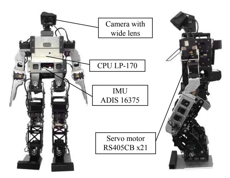
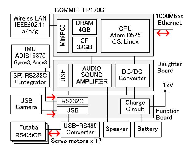
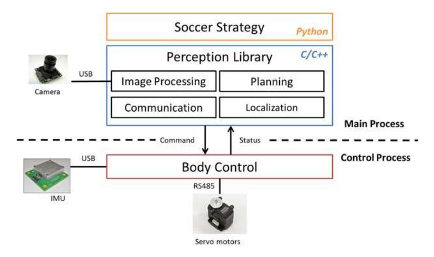
Table 1. Specification of the robot
| Weight | 4.2kg (Including Batteries) |
|---|---|
| Height | 600 mm |
| Velocity (Forward) | 0.4 m/s (maximum) |
| Walking Directions | All Direction and Rotation |
| (Select the Angle, Stride, Period and so on) | |
| CPU Board | COMMEL LP-170C (Intel Atom D525 1.8GHz) |
| OS | Linux (Ubuntu12.04LTS) |
| Interface | Ethernet x 1, USB x 1, |
| Speaker, DIP switch x4, Push switch x 1 | |
| Servo Motor | Futaba RS405CB x 19 |
| Battery | 3S (11.1V, 5000mAh ) |
3 Walking on the Artificial Grass
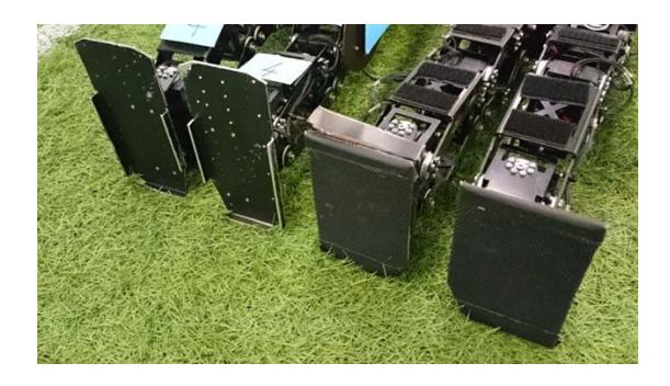
In 2015, the playing field was changed from a punch carpet to an artificial grass. Our robot attended the technical challenge "Artificial Grass" in 2014 and acquired the second prize of the challenge. Therefore, the robot has already walked on an artificial grass robustly from 2014. However, because the length of the artificial grass in RoboCup2015 was long (35mm), the robot could not walk robustly. Some teams used bolts attached to the sole for stable walking. We also tried to use bolts like other teams. Consequently, the stability of the walking was somewhat improved. However, it became more difficult to kick the ball. When the bolts touch the field during kicking the ball, a strong force is applied to the foot. For solving this problem, we assembled soles of the robot upside down and made the sole longer back and forth. We had already made long soles for the technical challenge "High-Kick Challenge" as shown in the Fig. 4. That helps to find the solution. The bent edges are attached to not step on its feet. Using the edges under the sole, the robot could walk robustly. Consequently, the walking speed on the artificial grass could be increased.
4 Ball Detection Method Using A Template
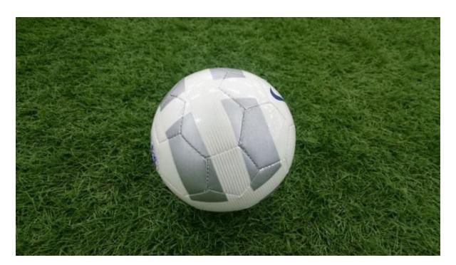
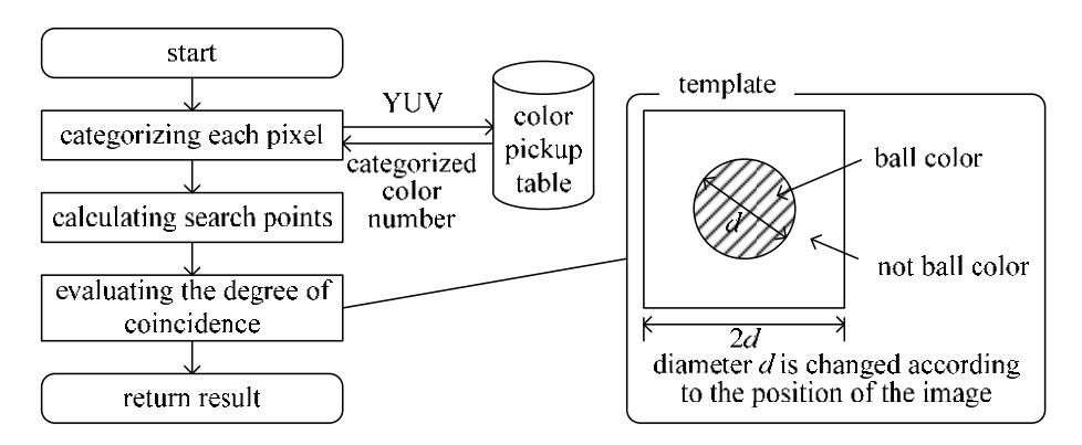
In the RoboCup2015, the real soccer ball was used in the game as shown in Fig. 5. The colors of the ball are just white and gray. The gray of the ball color is too similar to a shadow color of the goal or white line. Therefore, it was hard to distinguish the ball from other objects like goals and white lines using just color. Then, we tried to apply new detection method using the template of the ball as the Fig. 6. The sequence is the following:
- Categorizing each pixel to a color cluster according to a preset color pickup table
- Calculating search points around the previous ball position using a particle filter
- Evaluating the degree of coincidence by comparing a template data
- Registering as the ball if the maximum value is over a threshold
As the Fig. 6 shows, the template implies the shape of the ball. The size of the template is changed according to the distance to the ball. The degree of coincidence at each search point is calculated as the following:
- Picking 100 points up randomly in a rectangle of a search point
The rectangle corresponds to the template and the size of the rectangle is changed according to the distance of the ball.
- Calculating the degree of coincidence $Doc_k$ by comparing a template data of each point $P_{ki}$ in the k-th rectangle as the following equation:
$$X_{k} = {P_{ki} \mid C(P_{ki}) \text{ is ball color, } P_{ki} \text{ is inside circle} }$$
$$Y_{k} = {P_{ki} \mid C(P_{ki}) \text{ is ball color, } P_{ki} \text{ is outside circle} }$$
$$Doc_{k} = \frac{n(X_{k}) - n(Y_{k})}{n(P_{ki} \mid P_{ki} \text{ is inside circle})}$$
(1)
Here, C is the categorized color which is derived by using the pickup table. If the sampled image is completely same as the template, the degree of coincidence will be 1.0. Before using this method, we should set the pickup table for categorizing the ball. All colors of the ball are set as a just ball color. By using this method, the robot could detect the ball in about 3 meters robustly in our experimental soccer field.
Here, for detecting the ball robustly, the pickup table should be set as distinguishing the ball's white and other objects' white. The rate of this procedure was 5-10 frames per second.
5 Moving Ball Detection
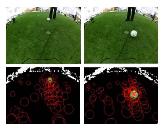
The robot could detect the stationary ball using the method described in the previous section. However, if the ball was moved speedily, the ball would be lost. Specially, that is a serious problem for a goal keeper. The main causes of losing the ball are a blurring of the ball image and a distribution of the search points. The problem of the blurring could be solved easily. It can be solved by adjusting a shutter speed. Another problem about the distribution is more complex. If the number of search points and the distribution will be increased, it will be possible to detect the moving ball. However, the cost of the calculation will also be increased. Here, a coming ball detection is more important for the goal keeper. Therefore, we modified the distribution of the particles like the Fig.7. The particles are distributed in accordance with a long vertical ellipse whose center position is slightly shifted to the bottom. By this modification, the robot could detect a moving ball robustly. Consequently, we succeeded in the technical challenge "Goal-Kick from Moving Ball".
6 Robot Strategy
The robot choose the best action by situation around oneself. The robot except the goalkeeper works in the same strategy. They judge a role from oneself by each situation and change it. Furthermore. We make an effort to develop a more flexible strategy in future. About the goalkeeper, we developed a new strategy this year. This strategy becomes independent with other robots and is specialized in the speed calculation of for exclusive use of the goalkeeper and the ball. I supplement the speed of a provided ball and predict it and save a ball.
7 Conclusion
In this paper we describe our humanoid robot system. We indicate the modification of the mechanism for stable walking and standing up on the artificial grass. Furthermore, we discuss the method to detect the new soccer ball.