Falconbots Team Description Paper RoboCup 2016
I.S.C. Julio Cesar Juarez Martinez, Alberto Adan Sánchez Morales, Alejandro Vazquez Garcia, Diana Laura Robles Juarez, Jesus Alejandro Añorve Gutiérrez, Adolfo Altamirano Ortega, Jorge Francisco Sánchez, Gerardo Juarez Martinez
Programa de Robótica y Mecánica del ITSSMT (PROMETEC), Technological Institute of San Martin Texmelucan Camino a la barranca de pesos S/N, 74120 San Martin Texmelucan, Puebla, México
http://www.itssmt.edu.mx/Estudiantes/parp.html
Abstract This paper presents the research done in the laboratory of Robotics and Mechanics ITSSMT for preparing to RoboCup 2016 in Leipzig, Germany. Research in the areas of computer science, mechanics, computer vision, walking techniques, among others mentioned are done. Falconbots has participated for five years in a row in the competition, 2011 in Istanbul, 2012 in Mexico, 2013 in the Netherlands, 2014 in Brazil and 2015 in China, thus having a considerable experience for racing. This article describes the specification and development of robots Falconbots team throughout the stakes in RoboCup.
1 Introduction
ITSSMT. The program of robotics and mechanical ITSSMT (PROMETEC) is a learning program born in August 2015, for students who are in any of the offered university courses at the Technological Institute of San Martin Texmelucan. The program includes various problems and challenges that are in the current society. In research conducted in PROMETEC, it is research in humanoid robotics. This research addresses various related issues, himself have been built since 2015 new prototypes manufactured in this project. The problems addressed in RoboCup competitions have made the team look into the need to improve the designs and prototypes created in the program. The Falconbots team has had a significant progress during their progress in RoboCup. The areas of computer science and artificial vision were only addressed as it was working with the robot DARwIn OP. Throughout the research the team has changed platform, handling robots such as Robonova, Bioloid and the aforementioned DARwIn OP. In recent years he has worked on creating its own platform to cover other areas of research, such as mechanics, inverse kinematics, balance techniques and electronics. We have worked with the Darwin OP platform and combined it with our platform to enable a more efficient taking into account some points of interest.
Commitment
The Falconbots team is committed to participate in the RoboCup 2016 in Leipzig, Germany and provide a knowledgeable arbiter of the rules of RoboCup humanoid league.
2 Mechanical structure
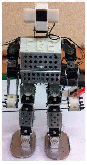
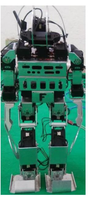
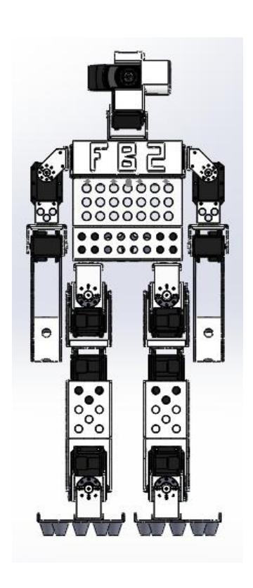
The structure of the robot with Falconbots counting equipment, robot FALCONBOT ONE and TWO FALCONBOT robot, equipped with the classic structure of 20 degrees of freedom, of which 6 are in each leg, each arm 3 and 2 head. Both robots meet the requirements to participate in the category KID size RoboCup humanoid. For mechanical structure two materials were used latest technology. 5052 aluminum used temple 32 for parts with increased load and torque applied and strategically aesthetic and functional pieces a 3D printer that handles ABS PLUS was used. Here the basic structure of both robots shown compared.
2.2 Sensor and actuator
The two robots 20 have DOF which are driven by a servomotor each. The actuators used for the movement of the degrees of freedom of the robots are the Robotis company in its series MX106, MX64 and Mx28. The engines are used in a specific position to exploit its torque and providing feedback to improve effectiveness without affecting the movement is used.
The robots use readings from various sensors to perform a study on the current status in space. These readings are based on general inertial body movement and support of the secondary unit to process them through a serial communication.
The camera is also a sensor that obtains a sequence of images to obtain position data in space and location of the objects of interest. The camera used to acquire and process images the Logitech C920. It is used in a resolution of 900 x 720.
2.3 Main Controller
To optimize computing resources and better system performance, especially the vision system and localization, Intel NUC computer is used with a custom operating system based on Linux. With an Intel Core i5 processor and 4GB of RAM, the system is optimized to maximize computing resources.
Ethernet and USB-Serial interfaces are used for communication with other devices are there in the robot.
2.3 Sub Controller
Development board STM32F4DISCOVERY is used to create a gateway to the main computer, which is used to send the inertial and position data in the space robot, in turn acts as an interface between the engine and control system.
3 Software
The control system and decision-making is scheduled MatLab with a main control module and the vision system, and c ++ and assembly for motor control and acquisition of inertial data through the gateway. The system is divided into 4 modules of interest:
- Artificial vision module
- Locomotion and kinematic control module
- Module filtering and interpretation of inertial data
- Localization Module
3.1 Artificial Vision System
In the competition of RoboCup in humanoid league, mostly in the category was established that the ball game, the goals and lines of the court were white, that means that most elements are there in the environment have a Color in common.
This makes difficult the collection of data of particular interest. In order to facilitate recognition of objects of interest within the vicinity of the soccer field, apply techniques to make the computational cost is cheaper and at the same time facilitate the recognition of patterns.
Image acquisition is done through the C920 camera in his YUV color space, to subsequently apply a Gaussian filter to improve the image basic medium. An algorithm for optimal recognition of light in the environment applies to level the native camera settings and so have the optimal image.
$$f(x) = ae^{-(x-b)^2/c^2}$$
Recognition of the ball and the goals is performed under two conditions, the first is to have only a pattern and unique colors for detection, ie, the minimum detected colors to save computational resource. The Kmeans algorithm is used to cluster with pixels. By applying the Gaussian filter and jointly kmeans algorithm, the result is an image with only 8 detectable and filtered to make a mapping of colors in which the target will be the important colors.
$$\underset{\mathbf{S}}{\operatorname{arg,min}} \sum_{i=1}^{k} \sum_{\mathbf{x}{i} \in S{i}} |\mathbf{x}{j} - \boldsymbol{\mu}{i}|^{2}$$
Later when the image is already in the core data, two sets of individual data are separated by applying a basic Hough transform algorithm, to detect patterns in a circle and patterns shaped line, and the ball correspondingly goals. All this is done through Octave.
3.2 Locomotion and behavior control
The behavior of the robot is based on the classic control system of finite state machines, where viewed from high level, this provides behavior based on the decision making process of the central control system. The main decision is based on what the vision processing system. A finite state machine high level controls movement of the body in general.
In low-level system of locomotion it is in kinematic analysis. The resolution of inverse kinematics is based on the resolution made by the team Darwin for robot DARwIn OP. Kinematic analysis is solved and through the technique of pendulum balance invested a stable ride is done. 20 DOF robot-like DARwIn OP, make the system locomotion much lighter and stable.
The center of mass of the robot is in the right spot to generate a higher speed in the FALCONBOT TWO, ONE unlike FALCONBOT.
4 Electronics
The electrical system of the robot Falconbot One is based on the robot DARwIn OP, with an CM730 controller for controlling the motors and sensors. A serial communication interface to a compass through the i2c bus was implemented. The compass sensor is implemented to cast the orientation of the robot on the field.
In the Falconbot two, the control system is based on the discovery SMT32f4 microcontroller, which serves as a gateway between the servomotors and the computer through a direct communication to UART2 serial bus.
5 Conclusions
This paper mainly introduce the details of FALCONBOT ONE, including its hardware configuration, electronics architecture, software architecture, and difference compared with FALCONBOT TWO.
References
- S. Behnke. Online Trajectory Generation for omnidirectional Biped Walking. Proceedings of the 2006 IEEE International Conference on Robotics and Automation. Florida, 2006, pp. 1597-1603.
- O. Chutatape, Linfeng Guo. A modified Hough transform for line detection and its performance. Pattern Recognition, 32(2): 181-192, 1999
- Stuart Russell, Peter Norvig, and Articial Intelligence. Artical intelligence a modern approach. Articial Intelligence. Prentice-Hall, Egnlewood Clis, 25, 1995.
- Dynamixel Robotis. Updated information available at: http://www.robotis.com/xe/dynamixel
- UM6 Orientation Sensor. Updated information available at: http://www.chrobotics.com