Team TH-MOS
Liu Xingjie, Wang Qian, Qian Peng, Shi Xunlei, Cheng Jiakai
Department of Engineering physics, Tsinghua University, Beijing, China
Abstract This paper describes the design of the robot "MOS series" and the improvements of robot MOS2016, which is based on MOS2015. The MOS series are used as a vehicle for humanoid robotics research on multiple areas such as stability and control of dynamic walking, external sensing abilities and behavior control strategies. Compared with the seniors, the improved robot has changes in both hardware and software, MOS2016 will be used in RoboCup 2016 competitions.
1 Introduction
TH-MOS has participated in RoboCup Humanoid League competition since 2006. The MOS robot works on DARwIn-op(Dynamic Anthropomorphic Robot with Intelligence, open platform) software platform with the platform developed earlier by the team, we improved the stability of locomotion and the artificial intelligence of the robot every year to perfect the robot. This year, we have many energetic and positive new teammates and we are working hard to finish a better robot. We focus on weight reducing, structure improving, appearance beautification, vision control and the software platform building.
TH-MOS commit to participate in RoboCup 2016 in and to provide a referee with sufficient knowledge of the rules of the Humanoid League.
2 Hardware and Electronics
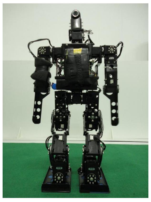
A photograph of MOS2016 is shown in Fig 1.
The whole structure does not differ a lot from MOS2015 but we are now working on a new cool robot shell. The links of the robot are mainly fabricated out of aluminum alloy to reduce weight and keep rigidity. In the past, in order to increase stability, the team enhanced the connection of shoulders and modified the structure of the chest. It is supposed to make the robot have better performance when falling down and getting up, as well as reducing the phenomenon of dropping small parts during the competition.
Our robot has twenty-one degrees of freedom (DOF): six in each leg, three in each arm, two in the neck and one in the waist. The DOF in the waist provides a bet-ter control performance of the robot when kicking the ball and getting up from a fall. Besides DOF configuration, the parameters of different parts such as leg length and ankle height are determined by simulation with gait generating algorithms to ensure better walking stability.
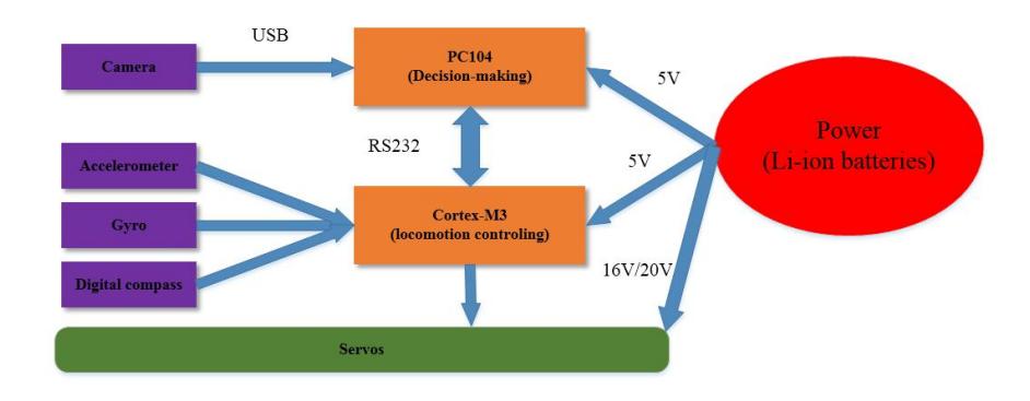
The electronic system of the robot provides power distribution, communication buses, computing platform and sensing schemes for the robot. For having a human-like sensation, we use the camera for its vision perception, a 6-axis sensor (connect 2-axis accelerometer, 2-axis gyro and 2-axis digital compass) for dynamic balanced control and servo motors. The architecture of electronic system is shown in figure 2.
As we can see, the electrical system is the same with former robots, but now we are considering replacing the old board card with DARwIn-op's board card. This plan is still in investigation and analyzation.
3 Software and Algorithms
The team transplanted DARwIn-op's algorithms into former software platform since MOS 2014. The port was modified between software and hardware, and used specific algorithms of DARwIn-op. This year specific algorithm and the main structure does not vary a lot. The software architecture is still composed of two layers. The first layer receives and processes messages from WLAN (used for team communication), digital compass, camera and joint position sensors. The second layer determines the behavior of the robot using results computed in the first layer and the directions from the controller box.
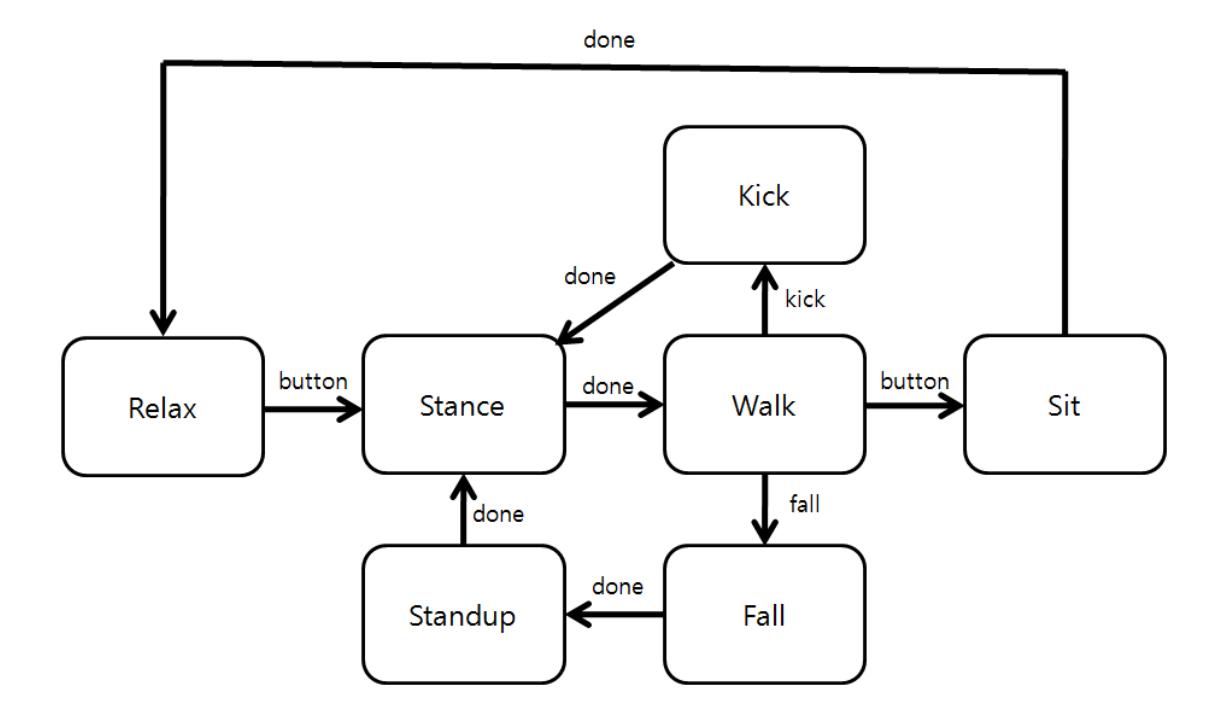
In the new algorithm, we use a finite state machine named Motion FSM to handle all low level body movements such as: standing up, walking, key frame motion, detecting fall, automatic stand up. The basic motion FSM is shown in figure 3.
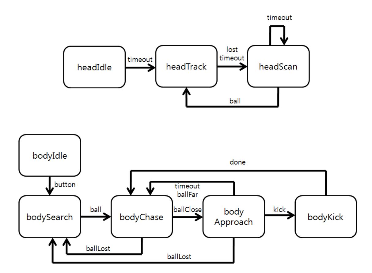
Besides, the MOS uses behavioral FSMs to control the robot which are finite state machines that govern high level behavior of the robot.Head FSM includes looking around to find the ball and trachking the ball if it is found. Body FSM includes searching the area until the ball is found, approaching the ball until the ball is close enough to kick, and kicking the ball. Figure 4 is body FSM and head FSM.
3.1 Omnidirectional Walking
The gait of most bipedal robots is controlled by precomputed trajectories, however, in robot soccer, a dynamic environment forces the robot to adapt their walking direction, speed and rotation to the changes [1]. A robot has to approach any point and module himself toward a preferred direction while avoid any collapse with obstacles on path. Based on predefined walking styles, complex path planning algorithm is needed. The generated series of gait can be eliminated when surrounding varies to some extent.
Our goal is capsulate the biped robot into an omnidirectional moving platform in the view of the mounted camera on head, and making gait parameterized with 3 pa-rameters: offset in forward and sidle direction and another rotation direction around Z axis.
Several walking strategies have been developed, most of which are based on the Three-Dimensional Linear Inverted Pendulum [2]. Firstly, foot trajectory is directly deduced from the foot planner from the gait command. Second, the center of pressure trajectory is defined based on ZMP discipline. COM trajectory is simply related to that of COP assuming the robot as a three-dimensional linear inverted pendulum [3][4][5]. Third, inverse kinematics generates joint trajectories based on the former foot and COM trajectories. An analysis resolution of inverse kinematics can be derived from the specific hip configuration of MOS 2013, which ensured the 3 joints intersected on a single point. [6] had issued the details of this method.
In our research, multiple formulas describing the trajectories are sampled, normalized, and saved in motion control board, and thus both of trajectory type and gain can be adjusted offline, and leaves joint trajectories generated online. An accelerating and decelerating algorithm is also developed to cope with a sudden change of walking speed command from behavior.
3.2 Vision Processing
The field lines can provide robots with a lot of useful information for self-localization and control strategies. In real-time competitions, the detection must be efficient. This year, we presented a novel method of line detection to meet the need.
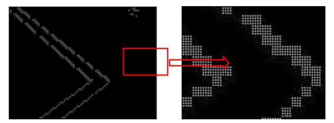
First, we scan the image with a large scan-step roughly. Then we make a local-precise scanning in regions where may be edge points. In this process, we use Sobel Operator to detect the edge points considering the limited computing ability of the CPU carried by the robot. We also add the limitation of the environment and the robot's camera to reduce the scanning time, and use an adaptive threshold of gray value, based on the change of gray value along the edge between white and green, to improve the accuracy. Fig. 5 shows the result of point extraction.
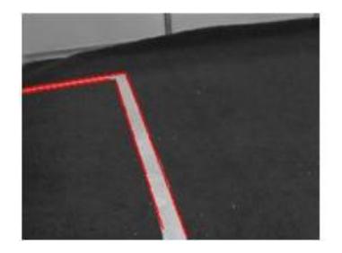
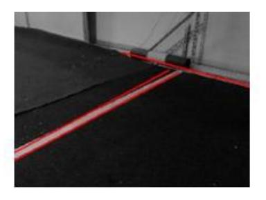
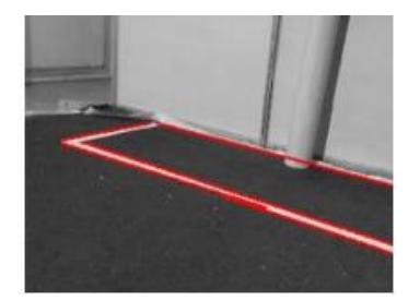
After all edge points are picked out, a modified Hough Transform [7] combining with the gradient direction of these points is used to extract lines. Thanks to the limi-tation of the gradient direction, many invalid calculations are avoided and the calcu-lating time is reduced greatly. In addition, to improve the accuracy, we also recalcu-late some important parameters. Fig. 6 shows the detection result of straight lines in different images.
It is important and useful to find the center circle for robots locating in the match. We proposed a method to find the center in three steps. First, we use the classical Sobel detector to process the original the image from the camera. And the center circle is usually ellipse in robots vision. Then, we transform the image based on the angle of the head steering engine. It will transform the ellipse to the circle. Finally, we use the randomized Hough transform (RHT) to find the center circle. And the circle will be found and it will help a lot for our robots locating.
3.3 Self-localization
Self-localization is a state estimation problem. The robot needs to estimate its position and orientation from the data of its sensors, mostly camera. We choose the widely used particle filter algorithm to solve this problem. The theoretical foundation is from 'Probabilistic Robotics', [8] and some ideas are from GT2005. [9]
The prediction, or control update, incorporates the states of particles with data from the odometer and IMU, and then some Gaussian noise is added. In the meas-urement update, we first incorporate the data from the camera and the compass, so we can distinguish similar landmarks and know their directions relative to the robot, and then we can update the states with this information. After that, we resample the particles. In this step, we're trying to keep as 'many low-probability particles' as possible. In the fourth step, we draw a final estimation from the particles, which can be used to make decisions in behavior algorithms. The state space is divided into 10x10x10 cellsand we find the 2x2x2 cube which has the most particles. The weighted average of particles in this cube is the final estimation.
The algorithm of initialization of particles is also important. We design different algorithms for different situation, such as initialization for just stand up, and initialization at the beginning of the match.
If the center circle is found, our robots will locate based on the information the center circle. It is not difficult to compute the distance between the robot and the center the field by using some optical knowledge and geometry skills. Then combined with the magnetic location which can get the information of the direction of robots, we can know the exact position of our robots.
3.4 Behavior
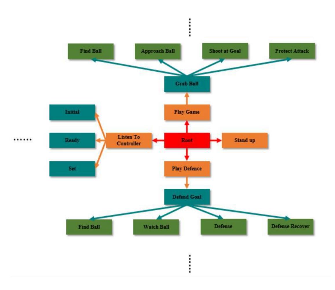
The architecture of the algorithms of robot behavior is based on a hierarchical state machine implemented in XABSL [10]. The architecture is composed of a series of options. A simplified option graph of robot behavior is shown in Fig. 7. The main task, which enables the robot to play soccer autonomously, is defined as the root option. The root option is separated into subordinated options until they become basic options, which can be executed by the robot. Those basic options include getting up from a fall, finding the ball, walking and kicking the ball.
Cooperation between robots is implemented on our robots. First, information such as ball location, robot location and current task of the robot is shared through WLAN. Furthermore, based on shared information, some kinds of team work of soccer are designed. For example, if two robots find the ball simultaneously, the robot that has a better condition in handling the ball will approach the ball while the other one goes another way. However, more complex multi-robots system cooperation is to be further developed on our robot platform.
4 Prior Performance in RoboCup
Team TH-MOS has participated in RoboCup Humanoid League competition since 2006. We are in the top-16 ranking list for 2012/13, and ranking second in technical challenge in 2013. This year , we believe MOS2016 will have a better performance with the efforts of generations.
5 Conclusion
This paper mainly introduce the details of MOS2016, including its hardware configuration, electronics architecture, software architecture, and changes.
References
- S. Behnke. Online Trajectory Generation for Omnidirectional Biped Walking. Proceedings of the 2006 IEEE International Conference on Robotics and Automation. Florida, 2006, pp. 1597-1603.
- S. Kajita, F. Kanehiro, K. Kaneko, K. Fujiwara, K. Harada, K. Yokoi, H Hirukawa. Biped Walking Pattern Generation by Using Preview Control of Zero-Moment Point. IEEE International Conference on Robotics and Automation. pp. 1620-1626, 2003.
- D. Gouaillier, C. Collete, C. Kilner. Omni-directional Closed-loop Walk for NAO, 2010 IEEE-RAS International Conference on Humanoid Robots. Nashville, TN, USA, 2010, pp. 448-454.
- J. Alcaraz-Jimenez, D. Herrero-Perez, H. Martinez-Barbera. Motion Planning for Omnidirectional Dynamic Gait in Humanoid Soccer Robots. Journal of Physical Agents, 5(1): 25-34. 2011.
- J. Strom, G. Slavov, E. Shown. Omnidirectional Walking using ZMP and Preview Control for the NAO Humanoid Robot. RoboCup 2009: Robot Soccer World Cup XIII. Springer, 2009, pp. 378-389.
- C. Graf, A. Hartl, T. Rofer, T. Laue. A Robust Closed-Loop Gait for the Standard Platform League Humanoid. Proceedings of the 4th Workshop on Humanoid Soccer Robots in con-junction with the 2009 IEEE-RAS International Conference on Humanoid Robots. Paris, France, 2009, pp. 30-37.
- O. Chutatape, Linfeng Guo. A modified Hough transform for line detection and its performance. Pattern Recognition, 32(2): 181-192, 1999.
- S. Thrun, W. Burgard, D. Fox. Probabilistic Robotics. MIT press, 2005
- T. Rofer, T. Laue, M. Weber, et al. German Team RoboCup 2005. [Online]. Available: http://www.germanteam.org/GT2005.pdf
- M. Lotzsch, M. Risler, and M. Jungel. XABSL a pragmatic approach to behavior engineering. Proceedings of IEEE/RSJ Intl. Conf. of Intelligent Robots and Systems.