KUDOS Team Description Paper for Humanoid Kidsize League of RoboCup 2017
Donghyun Ahn, Yunho Han, Soyeon Oh, Changmin Shin, Junghun Lee, Sungmin Han, Donghee Han, Hyebin No, Jisang Hahm, Minji Kim, Minchae Ham, Soomin Min, Seungmoon Jung, Semi Jang, Wonki Kim, Haeseung Song, Heejin Park, Baek-Kyu Cho
Robotics and Control Laboratory School of Mechanical System Engineering, Kookmin University, KOREA
http://rclab.kookmin.ac.kr · http://kudos.kookmin.ac.kr
Abstract We participated in the RoboCup 2016. Throught the competition we found our robot's strength and weakness. So we make an effort to improve robots. We applied elaborate PD control system to KUbot3 and KUboteen2. And we designed new robot, RoK(Robot of Kookmin Univ.) and we are studying new walking control algorithm which is based on the ZMP. In vision area we applied to all robots wider angle of view. After then, our robots work better so we expect to get better grades in the competition. This paper is brief description about our preparation and research for RoboCup 2017.
Keywords
KUDOS, KUbot3, RoK, wider view, PD control system, FT sensor
1 Introduction
We are KUDOS, which is an acronym of Kookmin University Dream of Soccer. We named our team so for two reasons. First, the ultimate objective of RoboCup is to held a team of robots that can win against the human soccer World Cup champions by 2050. Realizing this objective is the dream of robotics and soccer player. In this light, we chose dream of soccer as part of our team name. Second, kudos is a synonym of prestige. Because we aim to achieve prestige at the Humanoid KidSize League of RoboCup, the meaning of kudos well matches our team objective.
I try to introduce about our each teams. First, the control team performes to use the PD control to make stable walking for the KUbot3 and KUboteen2. Also we are studying about ZMP control to make more stable walking and we will adapt it to RoK (Robot of Kookmin Univ.).
Second, the vision team performes to make robots image processing to mask rapidly only the field and detecting the ball and goalpost. Furthermore, we make the algorithm of the goalkeeper robot by using the distance and the direction to the ball.
Rule of the RoboCup changes every year and goes to hard increasingly. Therefore we developed new soccer algorithms, walking control and design for robots.
2 Hardware
2.1 KUbot3
Our previous robots (KUbot1 and KUbot2) used Dynamixel MX-28. When the robots fell down, they have to stand up by action. This operation needs strong knee torque. But the power of the MX-28 is not enough to lift the robot. The MX-64 has more torque than the MX-28. Therefore, by replacing the knee actuator with MX-64, the KUbot 3 can operate more easily than the KUbot1 and KUbot2. Also, good results were obtained in kicking and walking.
2.2 RoK(Robot of Kookmin Univ.)
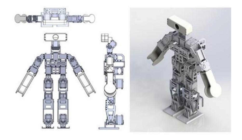
KUboteen2, who played in Robocup last year, used two motors to increase knee torque, but the pelvis has widened. As a result, the walking of KUboteen2 was unstable. So RoK was designed to complement it. RoK reduced the width of the pelvis by arranging the two motors of the knee in a vertical direction. In additon, by designing the legs in the form of four-link, the load on the knee motor is reduced. Also, FT sensor is attached to the ankle of the robot. Because FT sensor is necessary for ZMP control. The overall ratio of the RoK was designed by referring to the height and body ratio according to the age of the person.
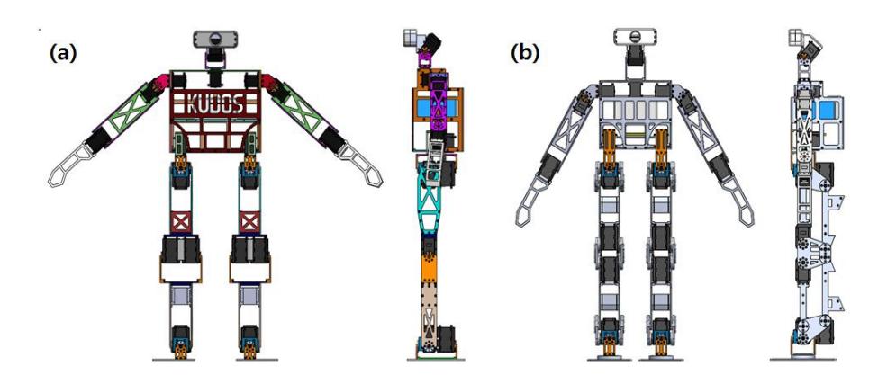
Table 1. KUbots Specification
| Series | KUbot3 | KUboteen2 | RoK | |
|---|---|---|---|---|
| Height | 479mm | 850mm | 856.8mm | |
| Weight | 3kg | 7.6kg | 6.7kg | |
| Number of DOFs | 20 in total | |||
| Actuator | DYNAMIXEL | DYNAMIXEL MX-64, MX-106 | ||
| MX-28, MX-64 SBC-fitPC2i |
Intel D34010WYK | |||
| Control Unit Main | Sub | CM-730 | ||
| Camera | logitech C920 | |||
| Intertia | Gyrosope:3-Axis L3G4200D, | |||
| measurement unit | Acceleration:3-Axis LIS331DLH | |||
| Other specs | Sound:speaker Display:body LED magnetometer:3-axis akm8975 |
Sound:speaker Display:body LED magnetometer:3-axis akm8975 FTsenser:3-Axis |
3 Algorithm for Robot Soccer
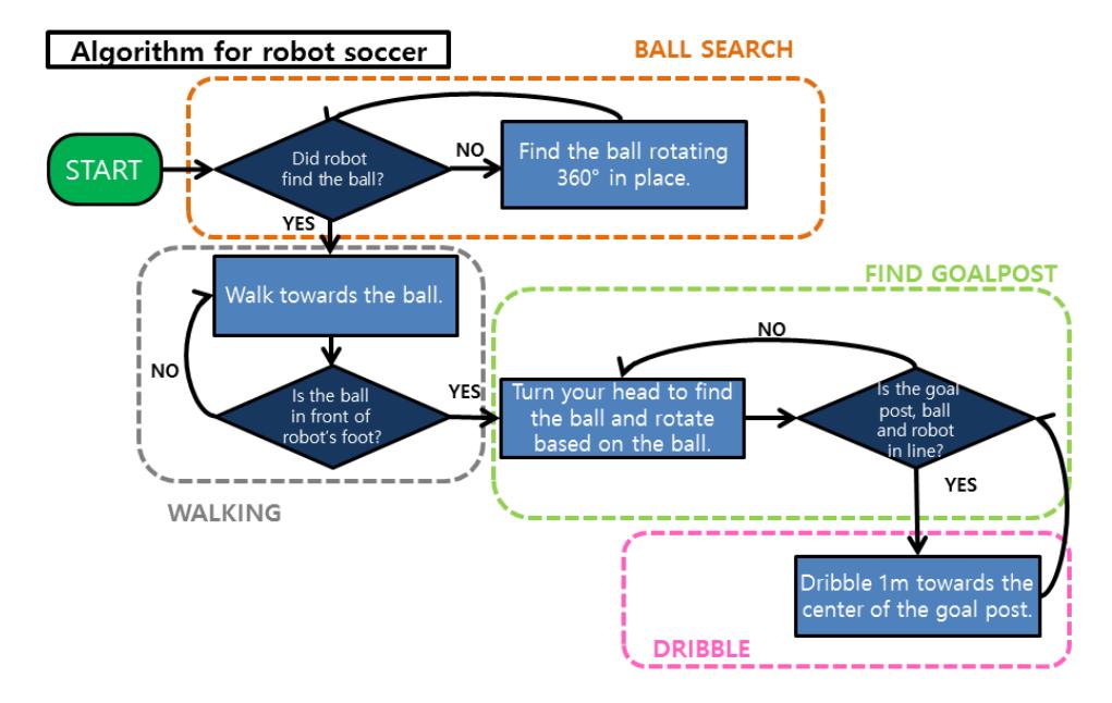
Robot soccer requires an accurate and sequential algorithm. Our robot soccer algorithm has following four steps.
In the first step, the robot searches for the ball by rotating 360 degrees in place. The second step is going towards the ball until the ball is in front of the robot's feet. The third step is to find opponent's goalpost by turning a head, and then revolve around the ball until the center of the goalpost, the ball and the robot are in a straight line. The fourth step is to dribble 1 meter towards the center of the goalpost. After 1 meter dribble, the robot turns a head again and checks walking direction. If the robot is on the straight line, dribble 1 meter. If not, revolve to be straight again. Then repeat the third and fourth steps until the ball enters the goal line. If the ball is stolen from the opponent, or robot falls, the robot will return to the first step of the algorithm to find the ball.
4 Vision
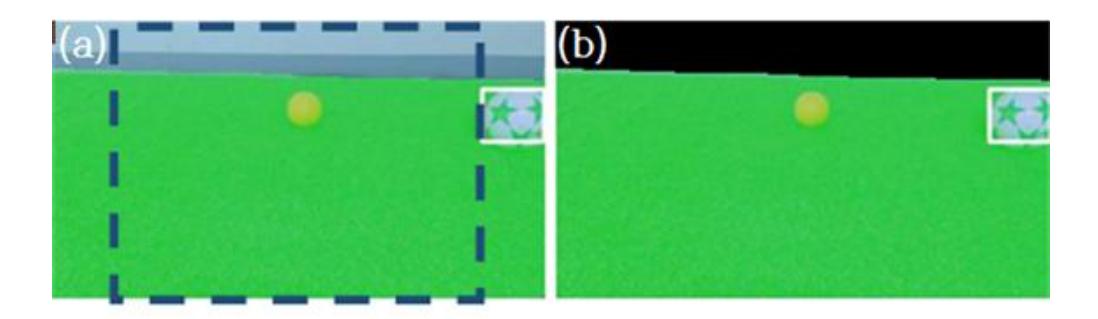
We upgraded to a wide-angle camera to get a wider angle of view. So, we could get 432x240 (16: 9) instead of 320x240 (4: 3) image screen, and it was possible to find the ball which was not visible due to the angle of view which is 1.33 times wider. However, as the number of screen pixels increases, the image processing speed is slowed down. So we excluded out of the field and over the horizontal line for image processing. Using the height and angle of the camera, we can remove the upper part of the horizontal line[1] and detect the green pixels to distinguish the field. We distinguish the field from surrounding with two processing. First, we distinguish the field based on width of frame. When approach each pixel of width gradually, start to scan up-and-down. If succeed in detecting the green, mark Field on those pixels. The second process will be similar to the first process, but repeat in a different order of width and height. Therefore, it is possible to reduce the computation speed by image processing only under the horizontal line and in the grass.
5 Locomotion
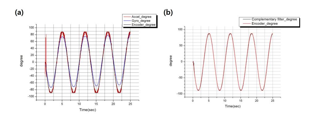
It is important for the robot to maintain the balance of the body in order to realize stable walking. But it is difficult because the grass field is not flat. Therefore, balance controller is necessary to the robot. We try to use PD control and ZMP control. First PD control is applied to the motor of the ankle pitch joint. For using the PD control, it is important to measure the current tilt of the robot. We used gyro and acceleration sensor to measure the tilt. However, the gyroscope contains error that comes from drift phenomenon. The accelerometer contains error that comes from noise. So we applied complementary filter to these sensor's data.
In Fig.5 (a), the lines are drawn by data of the encoder, acceleration sensor, and gyro sensor. It shows that the data, received by the gyro and acceleration sensor, can't catch up the data of the encoder. Fig.5 (b) shows the result after applying the complementary filter. It can be confirmed that the result catches up the data of the encoder. So we can measure the current tilt of the robot by using the complementary filter.
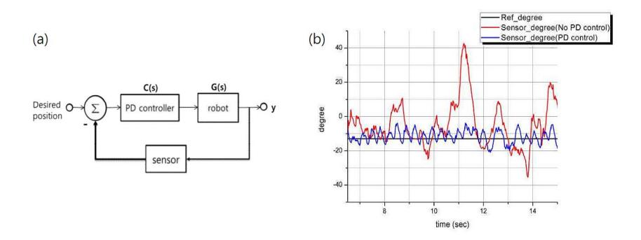
Fig.6 (a) is block diagram of the robot. C(s) shows the PD controller.
$$C(s) = K_p + s \cdot K_d$$
When the robot tilts, the target tilt of the robot can be maintained by applying the PD control to the motor of the ankle pitch joint. Consequently we can stand the disturbance acting forward and back. Fig.6(b) is a graph comparing the presence or absence of PD control when the robot is walking. When the PD control is not applied, red line can be confirmed that the tilt of the robot does not converge to the target tilt. On the other hand, when the PD control is applied, blue line can be seen that the tilt of the robot converges to the target tilt. By applying the PD control, the robot can walk stably on the lawn. Therefore, it is expected that walking is more stable in tournament and that we achieve better result.
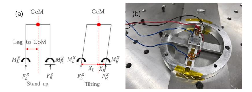
The word ZMP stands for Zero Moment Point. If ZMP is on the support polygon of the biped walking robot, it is stable. We need FT sensor for ZMP control. FT sensor measures the Force and Torque of the robot's ankle. Fig.7 (a) is free body diagram of the robot and (b) is FT sensor designed by ourselves. Following equation is ZMP equation using the FT sensor.
$$y_{zmp} = \frac{\tau_{x}}{F_{z}} = \frac{\int y F_{z}(y) dy}{F_{z}(y) dy} = \frac{M_{L}^{X} + M_{R}^{X} + X_{L} * F_{L}^{Z} - X_{R} * F_{L}^{Z}}{F_{L}^{Z} + F_{R}^{Z}}$$
To apply this ZMP control to the RoK, we are making FT sensor and studying the ZMP control. We will show better performance through the ZMP control at RoboCup 2017 in Nagoya.
6 Conclusion
We participated in the RoboCup 2016 and went up to the quarter-finals. Our team has been growing steadily as watching and learning other teams in RoboCup since 2013. We have been effort to grow up. We practice robot soccer every tuesday and hold a meeting to share and discuss about repective research every wednesday. Therefore our robots are improved in many fields of design, vision and control. We will participate in RoboCup regularly and grow further as a team. We aim to show much better performance in RoboCup 2017.
References
- Robo-Erectus Junior, Humanoid KidSize 2016 TDP, https://www.robocuphumanoid.org/qualification/2016/ 608cf71dcfb972d4844e4b84c6d7e283238cf5fd/ : Description Paper
- Team KUDOS, Humanoid KidSize 2016 TDP, https://www.robocuphumanoid.org/qualification/2016/ bd78a73af21d91cfa15200be3044306a0681d874/ : Description Paper
- Yunho Han, Baekkyu Cho, Walking humanoid robot controlled by Complementary Filter and PD Control : The 11th Korea Robotics Society Annual Conference
- Wanjin Kim, Baekkyu Cho, Walking humanoid robot controlled by Complementary Filter, PD Control and IMU sensor : The 11th Korea Robotics Society Annual Conference
- ZMP explaination, https://www.elysium-labs.com/robotics-corner/learn-robotics/ biped-basics/ : part of zero-moment-point-zmp/
- TaeYang No, Junho Oh, Development of a mechanically coupled, 6-axis Force-Torque sensor for Humanoid robots, Korea Advanced Institute of Science and Technology, 2006
- Shuuji KAJITA, Fumio KANEHIRO, Kenji KANEKO, Kiyoshi FUJIWARA, Kesuke HARADA, Kazuhito YOKOI and Hirohisa HIRUKAWA, Biped Walking Pattern Generation by using Preview Control of Zero-Moment Point, International Conference on Robotics and Automation, 2003
- Joseph Rudy, Zero-Moment Point Walking Controller For Humanoid Walking Using DARWIN-OP, 2014
- Gene F.Franklin, J.David Powell, Abbas Emami-naeini FEEDBACK CONTROL OF DYNAMIC SYSTEMS : CH3 Page 123 - 136, CH4 Page 196 - 211