Rhoban Football Club – Team Description Paper Humanoid Kid-Size League, Robocup 2017 Nagoya
J. Allali, R. Fabre, H. Gimbert, L. Gondry, L. Hofer, O. Ly, S. N'Guyen, G. Passault, A. Pirrone, Q. Rouxel
CNRS, LaBRI, University of Bordeaux and Bordeaux INP, 33405 Talence, FRANCE
http://rhoban.com/robocup2017 · http://metabot.cc · https://github.com/Rhoban/ForceFoot · https://www.e-consystems.com/industrial-digitalcamera.asp · https://www.ptgrey.com/blackfly-gige-poe-cameras · http://www.fit-pc.com/web/products/fitlet/
Abstract This paper presents a short overview of the design of the Kid-size humanoid robots Sigmaban and Grosban of the French Rhoban Football Club Robocup team. These robots are built to play soccer in an autonomous way. Main hardware and software components in their current state are presented, with an emphasis on major upgrades and research tracks for the upcoming Robocup 2017 competition.
1 Introduction and Last Participations
Rhoban Football Club is an on-going robotic project whose team members are researchers and PhD students at University of Bordeaux (France), CNRS and Bordeaux INP.
The interest of the team is mainly focused on autonomous legged robots and their locomotion. Our two leading projects are a small and low cost open source quadruped robot and kid to mid size humanoid robots with the RoboCup competition as major ambition (Sigmaban and Grosban platform). In this context, several prototypes have been built and tested [4,5,3,1] with a special emphasis on pragmatic and operational solutions.
The very challenging problem of robots playing autonomous soccer in complex and semi-unconstrained environment has driven the team to propose new mechanical designs – spine-oriented robot have been tested, low-cost foot pressure sensors are experimented – and software methods – new custom servomotors firmware, learning algorithms applied to odometry, motion generation and navigation problems.
Our participation to Robocup 2017, up to the qualification procedure, would be the sixth one:
– 2011 (Istanbul): Very first participation of the team at RoboCup competition under the name SigmaBan Football Club.
- 2013 (Eindhoven): Second participation under current name Rhoban Football Club. For the first time, the team was able to submit three robust humanoid robots without major hardware problem.
- 2014 (João Pessoa): We took a big step forward by reaching the quarter-finals and working out a robust walk engine.
- 2015 (Heifei): We coped pretty well with the new artificial grass and colorless field. We reached the semi-finals and took the third place of Kid-Size league.
- 2016 (Leipzig): Finally, we succeed to hit the first place of the Kid-Size league thanks to our versatile vision pipeline, an improved localization module through accurate odometry learning and the very beginning of high level team play strategy described in [2].
For this upcoming year, our expectation is to continue to enhance our robotics platform, to remove the use of the magnetometer in the localization module, to improve our navigation approach time as well as our kick engine by using learning and optimization methods.
This short paper gives an overview of the Rhoban robots hardware and software system in its current state with an emphasis on recent upgrades with the aim to participate to Robocup 2017 in Nagoya, Japan.
Commitment
The Rhoban Football Club commits to participate in RoboCup 2017 in Nagoya (Japan) and to provide a referee knowledgeable of the rules of the Humanoid League.
2 Hardware Overview
(section header only - content in subsections)
2.1 Mechanical Structure
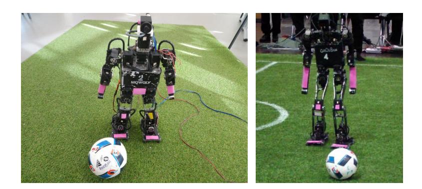
The mechanical structure of the robot is a classic design using 20 degrees of freedom: 6 for each leg, 3 for each arm, and 2 for the head (pitch and yaw rotations). The global shape of the robot is mainly standard.
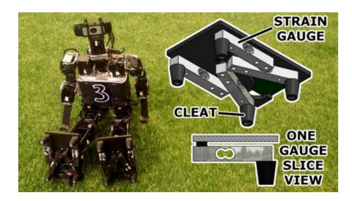
The main innovation of the robot is located in its feet. The feet are no longer flat but are put on the ground on top of 4 cleats at each foot corner. Only these cleats are in contact with the ground and "sink" into the artificial grass. This greatly improve the stability of the robot walking on the "soft" turf.
In addition to the ground contact, each cleat is linked to a strain gauge force sensor. The whole is integrated into the foot with a piece of electronics and the sensor readings are published on the Dynamixel bus as a virtual device. This low-cost force sensor allows for computing an evaluation of the center of (vertical) pressure for each leg. This sensor is greatly useful to stabilize the static kick, the walk engine and improve the accuracy of the robot's odometry. All mechanical specifications and electronics design and firmware are available as an open source project. See [6,7] for a more complete presentation.
Here are the main quantitative values describing the two robots:
Sigmaban Robot specifications
| Sigmaban Robot | Value | Unit |
|---|---|---|
| Degrees of freedom | 20 | |
| Weight | 4.2 | kg |
| Height | 57 | cm |
| Leg Length | 30 | cm |
| Arm Length | 27 | cm |
| Foot Length | 14 | cm |
| Cleat per foot | 4 |
Grosban Robot specifications
| Grosban Robot | Value | Unit |
|---|---|---|
| Degrees of freedom | 20 | |
| Weight | 4.5 | kg |
| Height | 75 | cm |
| Leg Length | 44 | cm |
| Arm Length | 38 | cm |
| Foot Length | 18 | cm |
| Cleat per foot | 4 |
2.2 Actuators and Sensors
All the joints are actuated by servomotors. We use off-the-shelf servomotors, that is, Dynamixel RX/MX-28 and RX/MX-64 for Sigmaban and Dynamixel MX-64 and EX-106 for Grosban.
The robot gets feedbacks through the following sensors:
- Inertial Measurement Unit. We use a 9 degrees of freedom IMU packaging a accelerometer, a gyroscopic and un unused magnetometer sensor providing both raws orientation (pitch, roll) information through serial communication. The component is a Razor 9-Dof IMU.
- Camera. The head of the robot is equipped with a Point Grey industrial camera of type Blackfly GigE on top of two (pan-tilt) servo-motors. It samples pictures with a resolution of 640x480 pixels with a frequency up of 25 Hz.
- Joint Positions. The robot uses also joint position feedback provided by each Dynamixel servo.
- Foot Pressure Sensors. Each foot has 4 stain gauge sensors integrated with the foot cleats and measuring the applied vertical force. An estimation of the (vertical) pressure point for each foot can be computed. This value is greatly use for stabilization control during walk and to estimate the robot's odometry.
2.3 Industrial Camera
Last year, we switched from standard webcam to a small USB3 industrial camera. The major advantages are the custom choice of the lens, and the global shutter sensor which highly reduce the motion blur.
However, its turn out that the USB3 communication cable interferes with the WiFi antenna, especially in jammed contexts such as RoboCup conditions. Thus leading to a very instable communication between our robots. So this year, we are currently testing a new type of industrial camera using an ethernet communication.
2.4 Processing Units
The embedded system is based on two main processing units: a small Cortex ARM7 microcontroller without operating system and a Fitlet from Fit-PC equipped with Linux (Debian 7). The Fitlet has 4GB of RAM and is based on quad core 1.2 GHz AMD Micro-6700T SoC while the ARM7 has 64kB RAM with 55 MIPS and run at 78MHz. More precisely:
The Fitlet is in charge of the high-level behaviour management and the execution of the high-level programmed components:
- High-level decision processes and behaviours. The behaviour of the robot is mainly driven by state machines and each different behaviours are implemented into C++ class.
- Walk motion generation. The walk generator is splines and inverse-kinematic based. It provides a high level omnidirectional control with forward, lateral and rotation velocities.
- Motion scheduling. Communication with low level servo-motors are clocked at about 100 Hz in Linux user space.
- Vision and localization module up to 25Hz..
- Communication with external entities (via WiFi IP protocol in development environment)
The ARM7 is in charge of the real-time low-level management:
- Sensors sampling and communication protocol.
- Servomotor control. The processing unit communicates with Dynamixel servos via a serial RS-485 bus.
We now describe in more details some of the above components, in particular the localisation module and the motion control system.
3 Localisation Module and Particle Filters
The localization module allows the robot to know approximately his position on the field. The estimation of the current position is used by the high-level state machine for taking decisions.
The localization relies on the analysis of the image to find the goal posts and field borders. Two particle filters are running continuously to integrate the detected features. The first filter maintain up to date the ball position with respect to the egocentric robot frame. The second one computes the absolute position and orientation of the robot on the field.
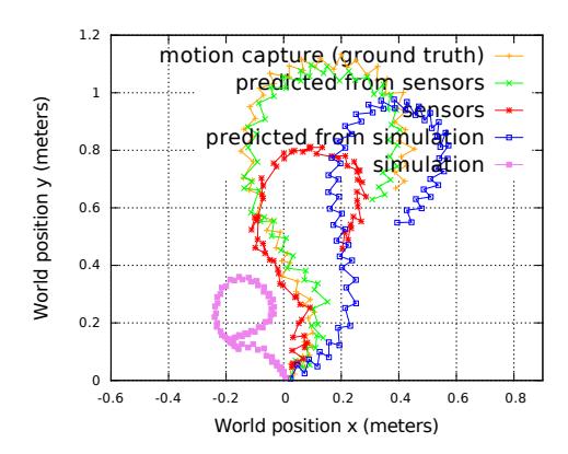
An essential basis for these filters accuracy is the odometry of the robot which integrates the known motion of the robot from internal sensors. The odometry is firstly computed from a complete kinematics model of the robot integrating each footstep using foot pressure sensors and servos feedback position. In order to significantly improve the accuracy and taking account of model discrepancies, ground contact slippery and unknown mechanical backslash, we correct in real time the computed odometry using a linear model trained without any external hardware. The original work was relying on a motion capture setup to record the actual robot's displacements. A more convenient calibration process have been developed for the RoboCup context. A complete presentation of this work is detailed in [8] and [2].
4 Motor Control
(section header only - content in subsections)
4.1 Markovian Decision Process Based Navigation
The navigation controller is the algorithm taking as input the game state, the ball and goals relative positions and issues orders to the walk engine in order to approach the ball in a good kick position. During all our previous participations, the navigation was expertly implemented as a state machine and tunned by hand. The far approach is satisfactory but the robot often takes too mush time at close distance from the ball to position itself in front of the ball with a correct orientation.
On our robots, accurate and fast close positioning is a difficult task since the walk displacements are noisy due to the grass unevenness, potential balance perturbations and the robot's mechanical and control inaccuracies.
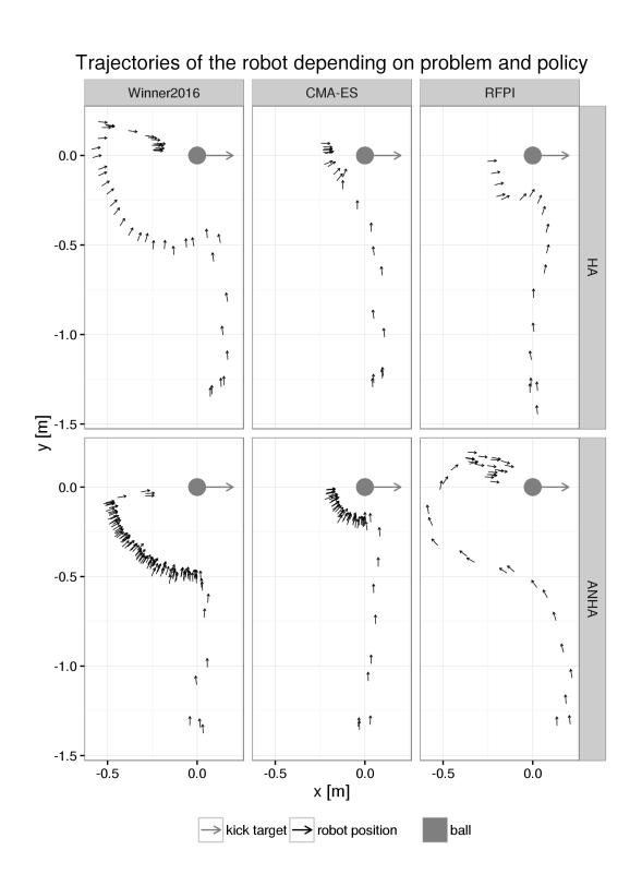
An ongoing project this year is to tackle this planning problem by using the Markovian Decision Process (MDP) formalism. A continuous state and action space MDP solver has been implemented and used to generate navigation policies. This solver uses a motion model accounting for actual deterministic walk displacements which is learned from an odometry calibration process. The model allows the MDP solver to generate a "feed forward" walk controller. The results of this method are displayed on figure 4.
This current work will be pursue and improved. We will try to use the same kind of technique using the MDP solver for high level strategic decisions such as kick power and direction.
4.2 Kick Motion Generation
Previous year in 2016, our kick motion was based on simple Cartesian and angular open loop splines crafted by hand. This kick is powerful but can not automatically adapt to several ball positions or kick powers. Moreover, since the mechanical parts of the robots constantly and slightly bend during the competition, regular human work is needed to re-tunned the motion over each robot.
Experiments are currently performed to automatically generate several kick motions using black-box optimization method. The kick motion is parametrized by a set of polynomial splines in Cartesian space. A complete dynamical model of the robot is used to evaluate the produced torques and Zero Moment Point (ZMP) position on a given kick trajectory. Then, the CMA-ES black box algorithm is used to optimize the spline parameters in order to find a balanced motion minimizing the joint torques. For example, the kick power can be controlled by imposing a specific velocity on the foot when the ball is expected to touch the ball.
However, the discrepancy between the expected target trajectory and the real robot motion makes the robot unstable for too high and dynamic kick power. Typical kick distance comparison are presented in Table 1. For now, the generated kick is not as powerful as our previous expert kick, but for low and medium power, the generated kick work on the real robot without any adaptation or manual tunning from simulation to physical world.
First results of kick distance order of magnitude on Sigmaban robot.
| Kick Motion | Generated 1.0 m/s | Generated 1.5 m/s | Expert 2016 |
|---|---|---|---|
| Rough Kick Distance (m) | 0.90 | 1.90 | 2.5 |
References
- Rhoban Robots at Yeosu International Expo 2012. http://rhoban.com/category/arms-2.
- Julien Allali, Louis Deguillaume, Rmi Fabre, Loic Gondry, Ludovic Hofer, Olivier Ly, Steve N'Guyen, Grgoire Passault, Antoine Pirrone, and Quentin Rouxel. Rhoban football club: Robocup humanoid kid-size 2016 champion team paper. In RoboCup 2016: Robot Soccer World Cup XX. Springer, Accepted.
- O. Ly, , M. Lapeyre, and P.-Y. Oudeyer. Bio-inspired vertebral column, compliance and semi-passive dynamics in a lightweight humanoid robot. In IEEE/RSJ International Conference on Intelligent Robots and Systems (IROS'2011), 2011.
- O. Ly and P.-Y. Oudeyer. Acroban the humanoid: Compliance for stabilization and human interaction. In IEEE/RSJ International Conference on Intelligent Robots and Systems, 2010.
- O. Ly and P.-Y. Oudeyer. Acroban the humanoid: Playful and compliant physical child-robot interaction. In ACM SIGGRAPH'2010 Emerging Technologies, Los Angeles, 2010.
- Gregoire Passault, Quentin Rouxel, Ludovic Hofer, Steve N'Guyen, and Olivier Ly. Low-cost force sensors for small size humanoid robot. In Humanoid Robots (Humanoids), 2015 IEEE-RAS 15th International Conference on, (Video contribution), pages 1148–1148. IEEE, 2015.
- Quentin Rouxel, Gregoire Passault, Ludovic Hofer, Steve NGuyen, and Olivier Ly. Rhoban hardware and software open source contributions for robocup humanoids. In Proceedings of 10th Workshop on Humanoid Soccer Robots, IEEE-RAS Int. Conference on Humanoid Robots, Seoul, Korea, 2015.
- Quentin Rouxel, Gregoire Passault, Ludovic Hofer, Steve NGuyen, and Olivier Ly. Learning the odometry on a small humanoid robot. In Robotics and Automation (ICRA), 2016 IEEE International Conference on. IEEE, accepted.