Elecatrón-Laredo – Team Description Paper Humanoid Kid-Size League, Robocup 2018
Eduardo Olvera-Castillo, Nayli Nohemi Gracia-De León, Jesús Geovanni Martínez-González, Raúl Francisco Aguilera-Hernández, Carlos Daniel Rico-Bernabé, Raúl Vázquez-Garibay, Jorge Oswaldo Rodríguez-Rodarte, Gabriela Abigail Hernández-Silva, Mauro Rolando Gallegos-Moreno, Martha Isabel Aguilera-Hernández (Mentor)
Instituto Tecnológico de Nuevo Laredo, Av. Reforma 2007 Sur, Col. Fundadores, 88000 Nuevo Laredo, Tamaulipas, México
https://www.femexrobotica.org/tmr2017/resultados-major/ · www.itnuevolaredo.edu.mx · mecatronteclaredo.jimdo.com
Abstract This paper presents an overview of the implementation and program design of Kid-size humanoid robots for playing soccer in an autonomous way. The robots are of the type Bioloid. The team "Elecatrón_Laredo" presents all the activities made as a group for preparation in participate for the upcoming 2018 competition.
1 Introduction
The team "Elecatrón-Laredo"is part of the Club Mecatrón of the technological institute of Nuevo Laredo, México. The club is an ongoing academic plan whose team members are from different careers in the institute. The group is interdisciplinary and are involved in different robotic projects. The club has been working since 2003. In 2004, when the Mexican robotic tournament (TMR 2004) start, the club participate mainly in the open category. After that the club has been participate in different categories like LARC OPEN, LARC SEK, and Rescue junior and major.
In 2015, the club participate for the first time in the Robocup Humanoide kid size category. The team was named mecatron_laredo. In this participation, the team only have two humanoids, and only one had a camera, a raspberry. After this participation, the club made some activities to collect funds and had the opportunity to buy the components to build two more, and equipped each one with cameras Havimo.
In December 2016, the team Elecatrón-Laredo, began to program the four humanoids. They made some modifications to the physical structure to make them walk better in different types of green carpets, to locate the ball and take it to the goal.
In March 2017, the team presents an exposition in the Mexican Tournament of Robotics of the north zone. This was held in the Cristobal Colon´s School in Escobedo Nuevo León. One month later, the team participate in the Mexican Tournament of Robotics in Naucalpan, Mexico city.
The group obtain the second place in the TMR 2017. https://www.femexrobotica.org/tmr2017/resultados-major/
After this participation, the group has been working in:
- a) Designing better algorithms for the vision system to locate the ball at more distance.
- b) Making parts using 3D simulation tools to get the robot more robust. Also a center mass analysis so the robot can walk more time in the green carpet without fall down.
- c) Designing algorithms for the vision system to recognize field markings.
- d) Making libraries to add to the ones that already exist for kicking the ball with more force.
This short paper gives an overview of the team robots. Presents the Bioloid hardware, the programming and the vision system in its current state. Also the recent upgrades with the aim to participate in Robocup 2018, Montreal, Canada.
Commitment
The team ELECATRON-LAREDO commits to participate in RoboCup 2018 in Montreal (Canada) and to provide a referee knowledgeable of the rules of the Humanoid League.
2 Hardware Overview
Our team works with four robots at this time. The type of the robots are bioloid. Two robots uses CM-5 control module and the other two uses CM-530.
The robots have been implemented with 18 degrees of freedom: 5 for each leg, 3 for each arm, and 2 for the head (pitch and yaw rotations).
One of the innovation made for the robots was in their feet. See Figure 3: Before and Figure 4: After. The feet was design in 3D simulator to improve the stability in the green carpet. We still working through design tools to make them more optimal in the field of play.
Each robot has a rechargeably battery pack (9.6V). In this way the robot can perform all the movements with the required energy.
The controller board uses serial connection to communicate with each of the servos. We use the Robo-Plus software to initialize the robots and to identified the servos. The software is combined 'C' programming language to add the communication with the vision system.
All the joints are actuated by servomotors. We use off-the-shelf servomotors, that is, Dynamixel DC for CM-5 and Dynamixel AX-12A for CM-530.
The specifications of the robotic team are shown in the following figures.
The robot gets feedbacks through the gyroscopic sensor providing information through serial communication that allow to know when the robot has fell down or change direction.
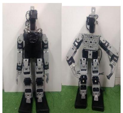
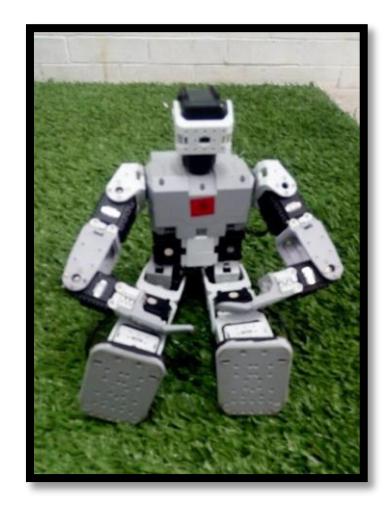
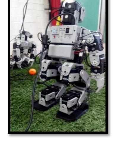

Figure 5: Robot Name, Taco - Specification sheet
| Measure | ROBOT NAME: TACO | |
|---|---|---|
| Weight | 2.017 kg 4.4467 lb. | |
| Height | 42.7 cm. – 16 13/16 in. | |
| Motor type | DYNAMIXEL AX-12ª | |
| Degrees of freedom | 20 | |
| Sensor type | GYRO GS-12, HaViMo camera (2.0,3.0) | |
| CPU | CM- 530 | |
| Walking speed | 17 cm./s. |
Figure 6: Robot Name, Teco - Specification sheet
| Measure | ROBOT NAME: TECC | |
|---|---|---|
| Weight | 1.865 kg. – 4.1116 lb. | |
| Height | 42.7 cm. – 16 13/16 in. | |
| Motor type | DYNAMIXEL AX-12A | |
| Degrees freedom | 20 | |
| Sensor type | GYRO GS-12, HaViMo cameral (2.0,3.0) | |
| CPU | CM- 530 | |
| Walking speed | 17 cm./s. |
Figure 8: Robot Name, Toro - Specification sheet
| Measure | ROBOT NAME: TORO | |
|---|---|---|
| Weight | 1.806 kg. 3.9815 lb. | |
| Height | 42.7 cm. – 16 13/16 in. | |
| Motor type | DYNAMIXEL AX-12A | |
| Degrees freedom | 20 | |
| Sensor type | HaViMo camera (2.0,3.0) | |
| CPU | CM-5 | |
| Walking speed | 17 cm./s. |
3 Vision system
The vision system is based in the Havimo cameras. The HaViMo 2.0 it samples pictures with a resolution of 160x120 pixels with frame Rate of 19 Fps. and the HaViMo 3.0 it samples pictures with a resolution of 2 megapixels with ARM Cortex M3 main processing unit.
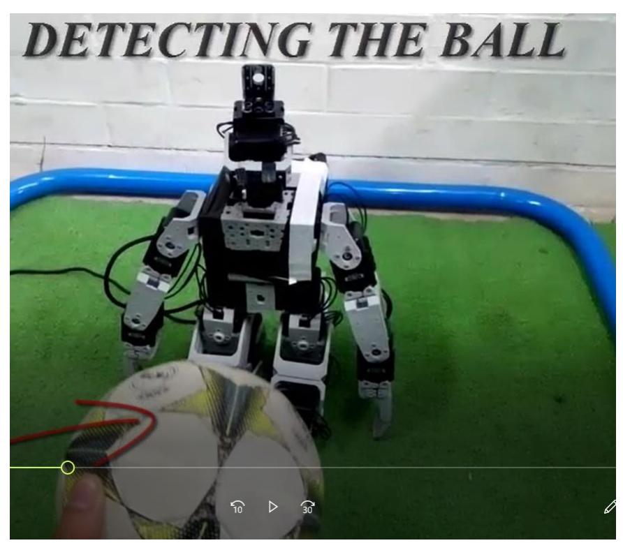
The algorithms in the vision systems has been designed in a modular way. Each module consists of special algorithms. This modularity in the system provide the option of growing without the problem of extended programs. The general algorithm of one module for the vision system is shown in figure 9.
Algorithm
The camera remains reading until the color of the ball is identified, when this happens a variable of the camera is modified wich is evaluated in the program.
While the camera detects the ball
A call is made to the function Get Bounding Box to obtain the coordinates of the detected object, are four locations, the maximum and minimum in x and y.
The coordinates of the function Get Bounding Box are averaged to obtain the coordinate x and y of the center point of the ball
This coordinate is used to determine if the ball is on the right, left or center of the camera Depending on the case the servomotor that functions as a neck performing horizontal movements of the camera, rotates to one side or the other following the ball.
-If it is centered on the robot
Take a step forward
If the ball is near the robot a certain distance
If the ball is centered
Kick the ball
Else (Adjust position)
If the ball is on the right
Take a short step to the right
If the ball is on the left
Take a short step to the left
-If it is on the right
Take a long step to the right
-If it is on the left
Take a long step to the left
If the ball is not detected, the function búsqueda_enfrente is called:
The servomotor of the neck has an intermittent rotation to the left until reaching a certain angle of vision.
Between each pause is called the function Get Bounding Box which in case of detecting the ball invalidates the cycle of búsqueda enfrente and the program continues.
If the angle can be reached then the same procedure is performed but with a right turn.
Figure 9: General steps of one of the algorithms of the vision system
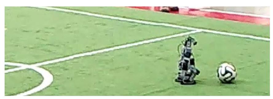
One of the main objectives to fullfill in the vision systems is to coordinate with a localization module. This allow the robot to find the field markings and the distance to them. An analysis to make a metric estimation based in an image has been make and the design of the algorithm has been done. The implementation in the robot will be functional by the tournament.
4 References
References
- Wail Mustafa, Mirko Waechter, Sandor Szedmak, Alejandro Agostini, Affordance Estimation For Vision-Based Object Replacement on a Humanoid Robot, ISR 2016: 47st International Symposium on Robotics, Proceedings.
- Ariffin, I. M., Rasidi, A. I. H. M., Yussof, H., Miskam, M. A., & Omar, A. R. (2016). Vision tracking application for mobile navigation using Humanoid robot Nao. In 2015 International Symposium on Micro-NanoMechatronics and Human Science, MHS 2015
- Baturone, F. J. Moreno-Velo, V. Blanco, J. Ferruz, "Design of embedded DSP-based Fuzzy Controllers for Autonomous Robots", IEEE Transactions on Industrial Electronics, Vol. 55, pp. 928-936 (2008).
- U. Franke, C. Rabe, H. Badino, and S. Gehrig, "6D-vision: Fusion of stereo and motion for robust environment perception," in 27th DAGM Symposium, 2005, p. 216.
- Do-Young Lee, Yan-Feng Lu, Tae-Koo Kang, In-Hwan Choi, Myo-Taeg Lim, 3D vision based local obstacle avoidance method for humanoid robot, 2012 12th International Conference on Control, Automation and Systems
- GUTIERREZ-Karina, AGUILERA-Martha, ORTIZ-Simón, ARRAMBIDE Gael, Aplicación de un Sistema de Reconocimiento de Formas y Colores en un Robot Humanoide. Revista de Tecnología e Innovación 2015, 2-2:315-321, Ecorfan.
- Tecnológico de Nuevo Laredo site: www.itnuevolaredo.edu.mx
- Club Mecatrón site: mecatronteclaredo.jimdo.com