SEU-UniRobot Team Description Paper Robocup 2018 Humanoid Kid-Size
Haidan Gao, Chuan Liu, Peng Wu, Le Zhang, Guidong Liu, Yu Wang, Qizhou Guo, Jiegen Shi, Wenhao Fan, Huwei Hu, Lintao Dong, Peiyu Tian
RoboCup Research Group, Southeast University, Nanjing, China
Abstract This paper presents the general hardware and software designs of the the Robocup Kid-size division team SEU-UniRobot for the Robocup 2018 competition in Montreal, Canada. A series of improvements will be discussed with an emphsis on robust field line identification and more accurate self-localization. In the end we will describe some problems we are working on.
1 Introduction and the Preceding Participations
Since the last year participation, we generally make a few adaptations listed below:
- 1.We have four brand new robots named Maxwell1, Maxwell2, Maxwell3 and Maxwell4. The number 1 and number 4 play for the striker or the guard, while the number 2 and number 3 serve as the goal keeper.
- 2.The camera is placed upright so that it can have a broader view vertically, simultaneously it needs not look up and down to search the goal while kicking the ball.
- 3.Even more powerful motors are mounted on the robots ankles, resulting in significant improvement for kicking ability.
The first time we participated in this competition was in July,2016 in Leipzig, Germany. We entered the quarterfinals that year, whereas some balls are kicked into our own goal due to the immature judgement for the goalside.
The Second time we participated in this competition was in July,2017 in Nagoya, Japan. Similar to the previous occasion, we also entered the quaterfinals. Nevertheless the insufficient mechanical structure cast shadows on our team performance.
Now it is our third time to participate in this competition. We hold a sincere belief that we can make more progress and spare no effort to contribute to this community.
2 System Overview
Figure 1 shows our four robot players, namely Maxwell1 - Maxwell4. Figure 2 shows the overview of our robots system from the hardware perspective.Figure 3 shows the overview of our robots system from the software perspective. Table 1 tells the specification of our robots.
As for the mechanical structure, Maxwell exploits a parallel push-pull rod structure, lost the flexibility of the forward tilt, in exchange for a more stable walking effect. It has a height of 81 cm, mainly composed of aluminum and carbon fiber.
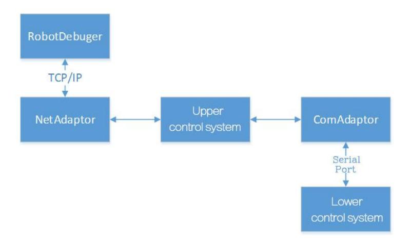
As for hardware structure, we devise our robots to use a hierarchical control system from top to bottom as shown in Fig.4. Futher details will be explained later.
As for software structure, a multi-threaded framework is adopted. Meanwhile a network adapter and a serial port adapter are specially connected with the debugging tools and the lower-level control system. See Fig.5.
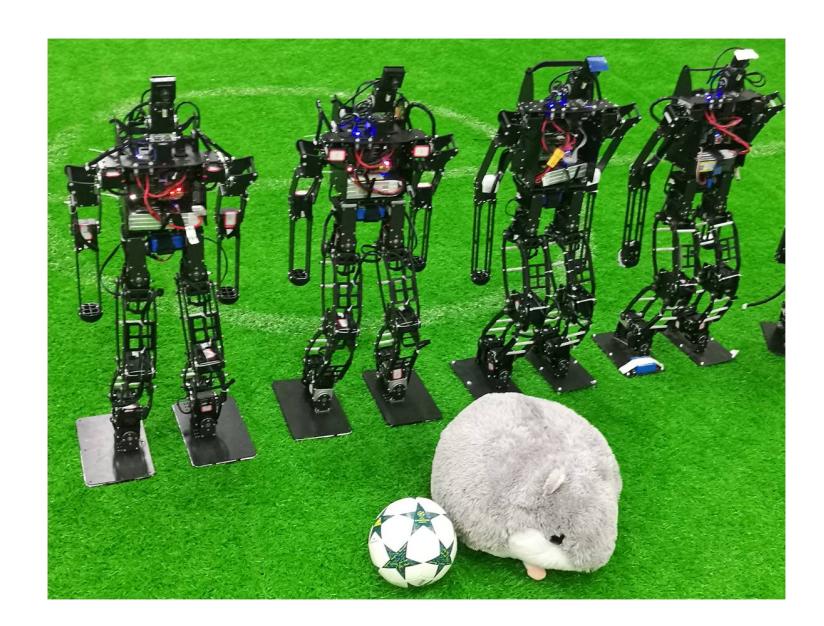
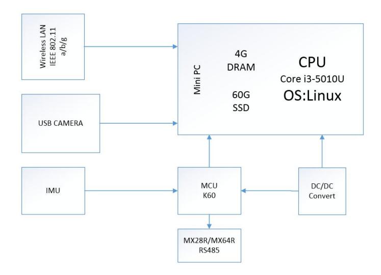
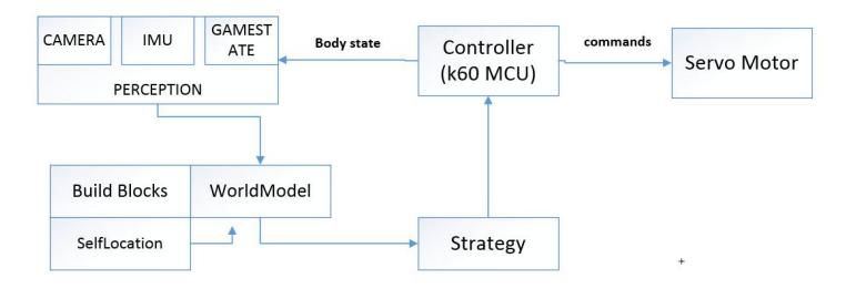
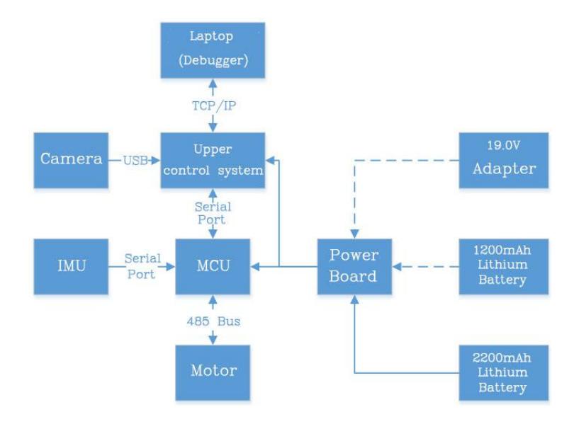
Table 1. Hardware System
| Weight | 3500 g(Including Batteries) |
|---|---|
| Height | 810 mm |
| Velocity(Forward) | 0.2 m/s |
| Walking Directions | All Directions |
| CPU Board | GB-BX(Core i3H-5010, 1.7 GHz) |
| OS | Linux(Ubuntu 16.04) |
| Interface | Ethernet x 1, USB x 2, Push button x 2 |
| Servo motor | MX-28R x 10, MX-64R x 10 |
| Battery | ACE(14.8v 3300 mAh) |
3 Hardware System
Our computer board(GB-BX) with Core i3-5010 CPU is typical of the high computational capability which is very significant for the robots. And a 60GB SSD is attached to the board for higher I/O speed. All of these are set to support the robot to react quickly in the fierce competitions. With this in mind, all software modules we develop including perception and control are executed on it.
4 Software System
As an improvement, we use Ubuntu 16.04 32 bit as our development environment this year for the better connection to the network. We make use of the router to connect with the robots, which supports for both LAN and WLAN connection. So we just edit and compile source code in our computers, debugging too of course. The WLAN provides us with an easy solution to sending files to robots so that we can code everywhere we like without any limitations. However, a direct connection between our computers and robots is also accessible with the Ethernet port when necessary.
Figure 3 shows the architecture of our software system. It is mainly composed of following three parts: perception, strategy and control. The perception part gets information from sensors and game controller. Images are captured by a USB camera and processed in the computer board. Useful information would be sent to the World Model as the sharing parts among processes. Based on these information, blocks like soccer and goal would be built up for self-location and strategies. Since external and internal information both prepared, the strategy part would generate relevant actions for the competition.
The body control tasks are operated in the dedicated control part. It not only controls the body according to the commands from the strategy part, such as walk or kick; but also periodically sends The status of the robot (e.g. posture) to the World Model. All these operations depend on sending relevant commands to servo motors by control process. Meanwhile, an IMU is used for gyro feedback and posture estimation.
4.1 Architecture
As an improvement, we use Ubuntu 16.04 32 bit as our development environment this year for the better connection to the network. We make use of the router to connect with the robots, which supports for both LAN and WLAN connection. So we just edit and compile source code in our computers, debugging too of course. The WLAN provides us with an easy solution to sending files to robots so that we can code everywhere we like without any limitations. However, a direct connection between our computers and robots is also accessible with the Ethernet port when necessary.
Figure 3 shows the architecture of our software system. It is mainly composed of following three parts: perception, strategy and control. The perception part gets information from sensors and game controller. Images are captured by a USB camera and processed in the computer board. Useful information would be sent to the World Model as the sharing parts among processes. Based on these information, blocks like soccer and goal would be built up for self-location and strategies. Since external and internal information both prepared, the strategy part would generate relevant actions for the competition.
The body control tasks are operated in the dedicated control part. It not only controls the body according to the commands from the strategy part, such as walk or kick; but also periodically sends The status of the robot (e.g. posture) to the World Model. All these operations depend on sending relevant commands to servo motors by control process. Meanwhile, an IMU is used for gyro feedback and posture estimation.
4.2 Perception
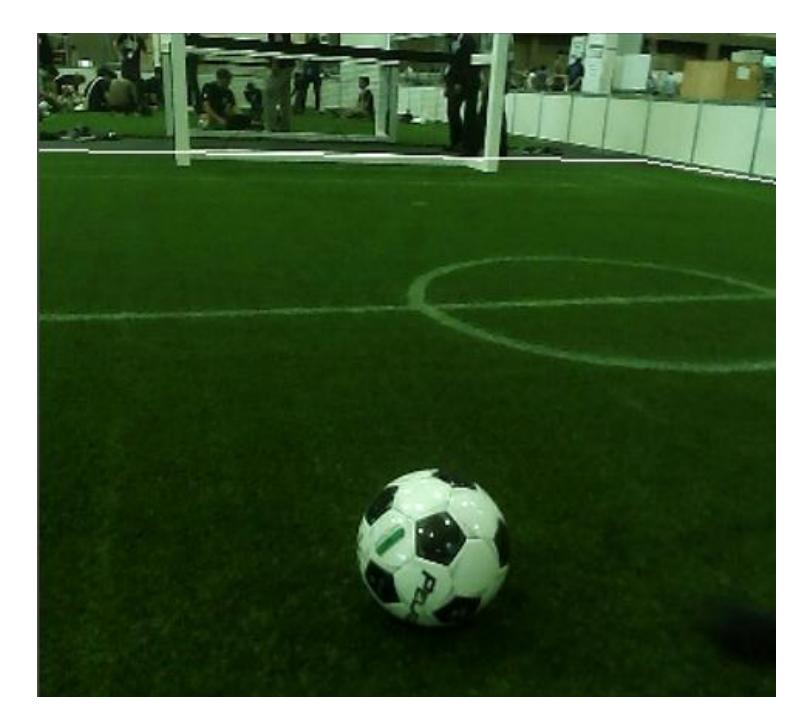
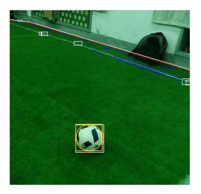
Fieldline recognition is improved by using convex hull and RANSC method. Firstly we use scanning lines to get candidate points that may represent the contour of the field. However some points will be inaccurate due to a ball happens to be at the bottom of the field or whatsoever. Thus convex hull are used to filter those inaccurate points. Finally we use RANSC to fit the points to get the fieldline. The effect can be seen from Fig.6.
Ball Detection Haar-like features and adaboost classifier are deployed for ball detection. Approximately 2000 positive samples which contains only the ball are collected. The number of negative samples is about twice the number of positive samples. Through an elaborated training, we get our classifier. Then we use size filter and color filter to improve the result, namely speeding up the recognization, reducing false recognition rate and improving the ball recognition rate at the foot. See Fig.7.
Goal Detection Goal detection is based on the detected fieldline. Firstly the scanlines run along the fieldline to search the area which is mainly white. This stage yields the positions where there might be a goal. Apparently that is not enough. Futher speculation is needed by scan vertically along the positions, which is got previously, to see whether it is still white for a certain length. By checking its width and using the ranging information we get to know the nearly accurate goal position.
4.3 Self-Localization
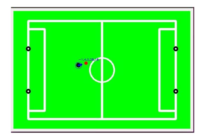
Self-Localization is improved by recognizing more landmarks such as fieldlines. Given an initial state, current position is checked consistently by examining the landmarks got in the image processing part. The possible positions are shown as particles. Those particles have the information of both position and pose. As the robot moves, the particles spread, indicating that uncertainty increases. As the robot stops, particles quickly converge to get a relatively accurate position and pose. The effect has been shown in Fig.8.
4.4 Strategy
We use two nested finite state machine for strategy control. External state machine is responsible for robotic start-up, standing up, kicking the ball and localization. Internal state machine is responsible for searching the ball, posture adjustment and dribble.
4.5 Body Control
Three different kinds of servo motors are applied on our robots, MX-106 for the ankles, MX-64R for the legs and MX-28R for other parts. The maximum torque of MX-64R is 64 kg-cm, which is sufficient to support robots' actions very well. Under the ZMP planning for motion, the robots get fast and stable mobility.
5 Conclusions
As shown in the previous section, our main improvements are fieldline detection and self-localization. Special attention should also be drawn to the fieldlines inside the border, which consists of the ring(we are currently working on), goal line etc. Judging from the last competition, our main drawbacks lies in the field of mechanical structure. Due to the incoordination between motion plans issued from control system and actual action performed by robot, upper strategy and perception system suffers a lot, resulting in an unsatisfactory result. However we are still busy preparing for the competition to be held in Canada, we believe futher improvements will be made.