UTRA Team Description Paper RoboCup 2019 Humanoid League (KidSize)
Jason Wang, Daniel Campoverde, Shahryar Rajabzadeh, Sabrina Lokman, Vaishali Iyer, Jeff Ma, Tyler Gamvrelis, Lukas Zhornyak, Nam Nguyen, Gokul Dharan, Hannah Lee, Izaak Niksan, Robert Fairley, Sherry Chen, Justin Yuan, Yuchen Wu, Carl Zhang, Pratham Desai, Armin Ale, Luis Camero, Lisa Zaher, Xiaoxue Xu, Chi-Hong Cheung, Edward Luo, Jorge Armijos, Tom Luo, Scott Zhang, Derek Lam, Diego Amores, Luis Munoz, Nyk Blozowski, Robin Lin, Xingcheng Huang, Hailin Wang, Max Hadley, (Skye) Zitian Wu, Zinan Cen, Aninda Poddar, Safeerah Zayheb, Russell Wang, Dhruv Warrier
University of Toronto, Toronto ON M5S1A1, Canada
http://www.utra.ca/teams/soccer/
Abstract This paper describes scientific aspects of team UTRA's humanoid robot named Bez for the Robocup 2019 Sydney competition. Changes in hardware and software since last year as well as current research interests and progress are stated.
1 Introduction
University of Toronto Robotics Association (UTRA) is a team composed of students from various disciplines: Electrical, Computer, Robotics, Chemical, Industrial, Mechanical Engineering as well as Computer Science and Architecture. The team's main goal is to promote education for students interested in the field of robotics. UTRA builds robots from scratch to allow students to learn technical and leadership skills necessary to work in a cross functional team. The mechanical, electrical, software, control and embedded subsystems have been designed entirely by students. The team's secondary goal is to make robotics more accessible to everyone. The biggest barrier of entry for robotics is hardware cost. This is a major obstacle for researchers, hobbyists and student teams. For this reason UTRA is pursuing semi-custom servo motor project which is described in more detail in last section.
2 Prior Performance at Robocup
UTRA participated for the first time in Drop-In category at Robocup Montreal 2018. During the competition the team faced many challenges which ranged from calibration, system integration to broken hardware. Despite those UTRA managed to play multiple games as goalie and deemed the first experience as successful. This year the team is working on improving existing systems with a big focus on upgrading software infrastructure and building testing equipment.
The following sections will describe current state of UTRA's humanoid robot named Bez, highlighting major changes since last year.
3 Mechanical Subsystem
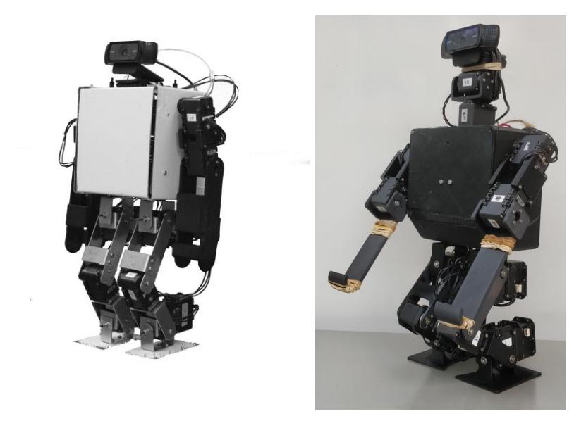
Since last year's submission, UTRA has developed a new version of the robot. The first model (depicted on the left in figure 1 ) was fully constructed from aluminum and used sixteen Dynamixel AX12 motors [1]. Since then the Mechanical team has built an improved version shown in fig1 on the right. A notable change is that all the parts of the robot are 3D printed. This helps reduce manufacturing effort and increases precision over handmaking metal components. The torso is completely redesigned to better accommodate various electronics and make them accessible for connecting peripherals during testing. Two motors have been added to the neck to enable the robot to look around and the legs have been upgraded from Dynamixel AX12 to Dynamixel MX28 motors — in total there are 12 new motors in the legs. These motors provide more torque and better control.
4 Electrical Subsystem
The electrical team is responsible for designing the PCB that houses the microcontroller and its peripheral circuitry. A new PCB has been manufactured since last year's submission which helped reduce original ciruit size. The buffer circuitry lets the microcontroller read and write to the Dynamixel smart servos that utilize half-duplex TTL UART interface for communication. There are 5 of such buffer circuits on the PCB which allows 5 independent daisy chain of servos that microcontroller can use to communicate with 5 servos at the same time. This helps decrease communication latency which is crucial for active control during walking.
The battery inside the robot is a 3-cell 2200mAh LiPo variant that powers all electrical components of the robot: Microcontroller PCB (which provides power for the servo motors) and Nvidia's Jetson TX2 computer module accompanied by the Orbitty carrier board from ConnectTech Inc.
5 Embedded Subsystem
embedded software performs low-level actuation and sensing functions — unlike last year, it does not execute control algorithms for the robot, nor does it have static trajectories. The software is written in C++, documented using Doxygen, and uses Google Test/Mock for unit testing. We have populated our GitHub wiki with tutorials for getting started with these tools in the context of embedded development. All the software was written from scratch with the exception of FreeRTOS and ST's HAL. Versions of the software are actively developed for the STM32F446RE and STM32F767ZI microcontrollers, and the F4 version is currently in use in the robot.
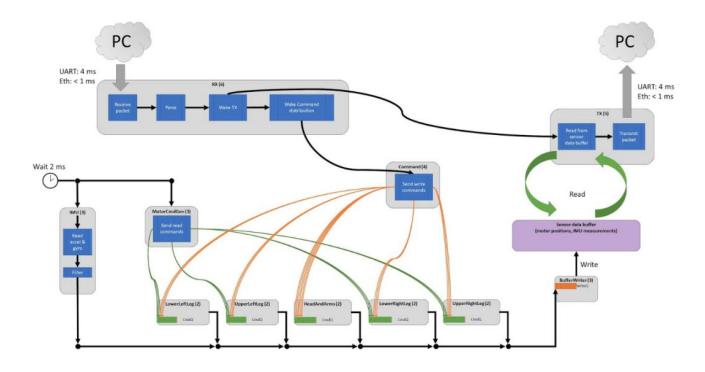
A system-level diagram for the embedded software is shown below. Each grey box is a thread and the number next to the threads name is its priority (higher number implies higher priority).
Actuation
12 Dynamixel MX-28s form the legs (4 daisy chains of 3 motors), and 6 Dynamixel AX-12As form the arms and neck (1 daisy chain). In software, each daisy chain has its own queue into which commands to update the goal position and read the current position can be sent, as well as its own thread to service the commands. When the microcontroller receives a packet of goal angles from the Jetson, it distributes the write commands among the queues and the threads initiate asynchronous transfers via DMA to update the goal positions of the smart servos.
Sensing
The parts of the software related to retrieving sensor data — current positions for the legs and inertial measurements (MPU6050) — are time-triggered. Fresh sensor data is collected every 2 ms.
Communication
UART and a virtual serial port are used to transfer data between the Jetson and microcontroller. The packets sent and received are of identical structure, and take 4 ms to transmit at the current symbol rate of 230,400. Because tests with Ethernet on the F7 demonstrated less than 500 µs mean transmission time under busy CPU conditions and Global EDF scheduling on the Jetson side, this communication system will likely be pursued in future designs.
6 Control / Software Subsystem
Mechanical Control
Leg trajectories are determined using inverse kinematics. First a fixed trajectory for the robots body was generated. Using this trajectory for the body, two footstep trajectories were determined alongside the robot body to move the robot from point A to point B. The locations of the footsteps were then calculated. Inverse kinematics was calculated to move the robot whilst maintaining balance. A multi state PID controller using the yaw and pitch angles of the robot as feedback was used to stabilize the movement
Robot Strategy
A Hierarchical state machine was used to determine the basic strategy of the robot based on the inputs. A simulink stateflow block and simulink publishers were used to be able to test the robots state transitions quickly from a remote computer
Team Communication
A serverless UDP system was built for communicating between robots. Information passed between the robots include states and localization information. This is yet to be implemented to improve the localization of the robot.
Computer Vision and Localization
Using Hough Lines and projections to get the field lines from the screen onto the 3d ground. Monte-carlo localization to get the location of the robot on the field
Navigation
RRT (Recursively random trees) was used to make path decision based on obstacles. The trajectory was generated in advance and will be regenerated in the case of a fall or being blocked by an obstacle
System Architecture
A multi agent docker setup was created to be able to simulate multiple robots using ROS and Gazebo
7 Current Research
Our current control algorithms use position control for actuation (i.e. sending angles to the servos) and require the current position from each joint to be sent back from the servos. The Semi-custom servo project is looking at the feasibility of modifying the hobby servo motors that are position-controlled via the duty cycle of the PWM input fed to their internal control circuitry. The hobby servos that output similar stall torque and no-load speed while being less than half the price of the Dynamixel servo motors are selected for our tests. Using a linear potentiometer to provide the position feedback for the control circuitry inside the hobby servos is common. With some reverse engineering, the output from the potentiometer whose voltage varies with the change in position should be exposed. To make the hobby servo behave as an smart servo, a small microcontroller-based circuit is added. The microcontroller is responsible for providing the correct PWM waveform to the hobby servo and read the linear potentiometer via its Analog to Digital Convertor (ADC). To communicate with the main microcontroller, the same buffer circuitry used in the main microcontroller PCB can be used to facilitate half-duplex TTL UART communication. Using the hobby servos spares the effort of dealing with mechanical side of the servo motors while the form factor is very similar to the smart servos.
The final product of this project is a small add-on board that can turn many of the available hobby servos to smart servos with limited capabilities while working alongside other types of smart servos.
References
- Jason Wang, Shahryar Rajabzadeh, Tyler Gamvrelis, Lukas Zhornyak, Nam Nguyen, Newton Xu, Mariko Tatsumi, Arnav Goel, Walton Wang, Justin Yuan, Steven Liu, Yuchen Wu, Gokul Dharan, Izaak Niksan, Jenny Yang, Xu Xiaoxue, Omer Faruque, Samee Mahbub, Jeffrey Qiu, Gallop Fan, Ganeshan Sivakumaran, Kyle Kim, Daniel Campoverde, Robin lin, Steven Lee. UTRA Team Description Paper Robocup 2018. Available online at https://www.robocuphumanoid.org/qualification/2018/KidSize/UTRA/tdp.pdf