NimbRo TeenSize 2006 Team Description
Sven Behnke, Michael Schreiber, Jörg Stückler, Hauke Strasdat, Maren Bennewitz
Albert-Ludwigs-University of Freiburg, Computer Science Institute, Georges-Koehler-Allee 52, 79110 Freiburg, Germany
Abstract This document describes the RoboCup Humanoid League TeenSize team NimbRo Albert-Ludwigs-University Freiburg, Germany, as required by the qualification procedure for the competition to be held in Bremen in June 2006. Our team uses self-constructed robots for playing soccer. The paper describes the mechanical and electrical design of the robots. It also covers the software used for perception, behavior control, communication, and simulation.
Introduction
The project NimbRo – Learning Humanoid Robots was established at Albert-Ludwigs-University Freiburg, Germany, in 2004. Our TeenSize team participated with success at last year's RoboCup Humanoid League competition in Osaka, Japan. We won the Penalty Kick competition. Our robot Max scored 3:0 in the final against Aria (Iran). It also was the best TeenSize robot in the Technical Challenge. This resulted in the third place in the overall Best Humanoid ranking, which combined teams from both size classes.
For the 2006 competition, we prepare not only for the Penalty Kick, the Technical Challenge, and the Race Walk, but also for 2 vs. 2 soccer demonstration games.
This document describes the current state of the project as well as the intended development for the 2006 RoboCup competitions. It is organized as follows. The next section describes the mechanical and electrical design of our robots Max and Fritz. Sec. 3-5 cover perception, behavior control, and infrastructure, respectively.
Robots
Robot Max
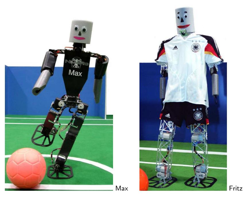
The left part of Fig. 1 shows our robot Max, ready to kick the ball. It is the larger sibling of our KidSize robots Jupp and Sepp [3]. Max is 75cm tall and has a total weight of 2.4kg. The robot is driven by 19 servos: 6 in each leg, 3 in each arm, and one in the trunk. Its mechanical design focused on human-like proportions and light weight.
Max is fully autonomous. It is powered by Lithium-polymer batteries. Three HCS12 microcontrollers generate target signals for the servos and read back the servo positions and duties. They also interface an attitude sensor consisting of two accelerometers and two gyros as well as an electronic compass. The microcontrollers communicate with each other via a CAN bus and with the main computer, a Pocket PC, via a RS232 serial line. This Pocket PC is equipped with a wide-angle CF-camera.
Robot Fritz
Fritz, depicted in the right part of Fig. 1, is 120cm tall and has a weight of about 6kg. It played as goalie in the RoboCup 2005 Penalty Kick competition. The robot is driven by 16 servos: 5 in each leg and 3 in each arm. While we used the Futaba S9152 digital servos for the arms, the legs needed stronger actuators.
Unfortunately, large digital servos are not available on the market. Hence, we used the analog servos PS-050 made by Tonegawa [8] in the legs of Fritz. These servos have a weight of 290g and a torque of 110kg·cm when supplied with 12V power.
In analog servos, the internal controller is synchronized to the 50Hz pulse train that encodes the target position. A typical problem of analog servos is that they suffer from large position tracking errors and variations of the zero-position which are caused by changes in temperature and/or supply voltage.
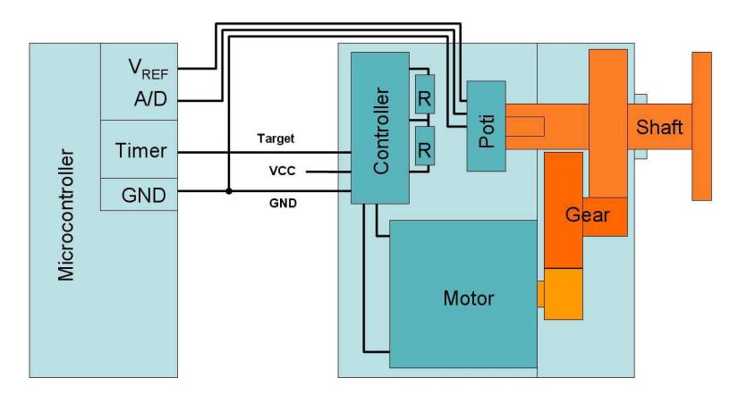
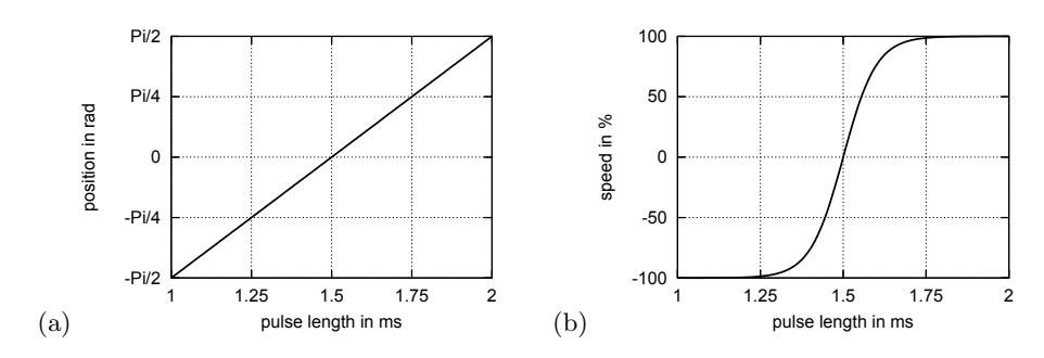
To improve position control, we modified the Tonegawa-servos by replacing, in the internal circuit, the potentiometer with two equivalent resistors, as shown in Fig. 2. From the perspective of the internal controller, the servo shaft now seems to be always in the middle position. This changes the meaning of the pulse train sent to the servo from a target position (see Fig. 3(a)) to a target speed. 1.5ms pulses yield zero position error. Hence, the motor is not driven and the servo does not move. 1ms pulses yield the maximal negative position error and the motor is driven fully to the left. Symmetrically, 2ms pulses make the motor turn right with maximal speed. The resulting sigmoidal pulse-length-to-speed curve is shown in Fig. 3(b). Servos modified in such a way have been used in many wheeled robots, like the Palm Pilot Robot Kit [5], and Hancor [4].
The mechanical connection between servo shaft and the potentiometer is left unchanged, but the potentiometer is electrically disconnected from the internal servo controller and is interfaced to the A/D converter of a HCS12 microcontroller. The microcontroller now can read the potentiometer voltage, which corresponds to the shaft position. It compares the actual position with the target position and issue motion commands, encoded as pulse train, to the servo. The pulses are generated with 16Bit accuracy by the timer module of the microcontroller.
This digital position control is much more flexible than the internal servo controller. Because the controller is now described in software, it is easy to implement more complex control strategies. For example, a full PID-controller [6] can be realized by observing not only the current position error, but its integral and derivative as well.
Systematic comparative test between an unmodified analog servo in the one knee and a digitized servo in the other knee showed that long-term position errors can be avoided by integrating the short-term error. This was particularly useful to correct for drifts in the zero-position of the analog servo, which are caused by changes in temperature. The error derivative could be used to damp overshoots.
In contrast to hardware controllers, it is easy to change the parameters of the implemented software controller. This can even be done on a fast time-scale, yielding an intelligent actuator that can be configured not only by the target position, but also by control gain, maximal speed, etc. Such an on-the-fly configuration makes it possible to adapt the control to changing load conditions. We implemented a slow startup behavior that avoids mechanical stress and overshoots when the controller is switched on.
Finally, the microcontroller can easily provide feedback about the current state of its controller to higher control layers. Quantities of interest include the current position, the position error, the integrated error, and the issued motion command.
Fritz is also powered by rechargeable Lithium-polymer batteries. Its main computer is an ultra-portable PC. The Sony U750P has a weight of 550g, including batteries, and features an ultra-low voltage 1.1GHz Pentium M 733 processor, 512MB RAM, 20GB harddrive, a touch-sensitive display with SVGA resolution, and wireless LAN. This PC is interfaced to two ultra-wide-angle USB cameras. They consist of webcam electronics, a 1/3"CCD imager, and a door viewer lens.
Perception
The main computers of Max and Fritz run behavior control, computer vision, and wireless communication [1].
Our robots need information about themselves and about the world around them to act successfully. We fuse the accelerometer and gyro readings to obtain an estimate of the robot attitude. We also estimate the heading direction from the electronic compass and keep track of leg joint angles and motor duties.
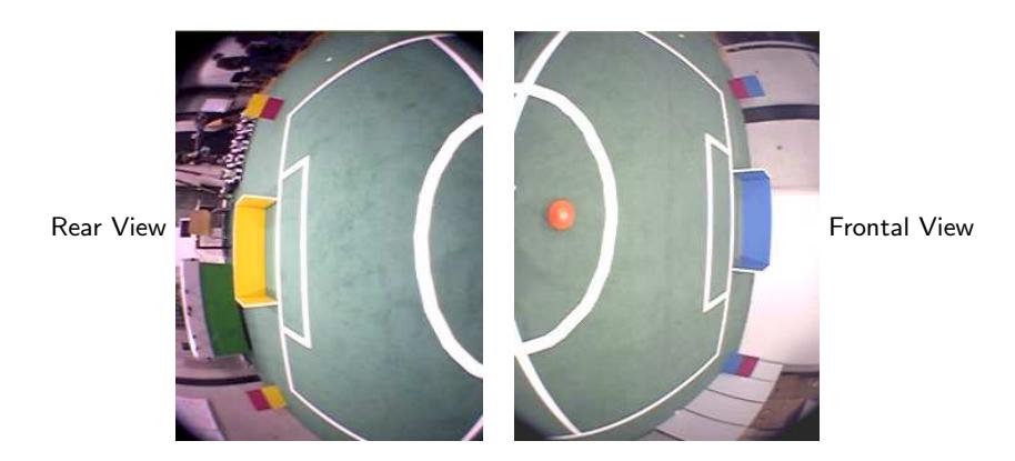
The only source of information about the environment of our robots is their camera. The wide-angle CF-camera of Max allows it to see its own feet and objects above the horizon simultaneously. The USB-cameras of Fritz can see almost all objects around it when they are pointed towards the front and the back of the robot. Two images captured simultaneously are shown in Fig. 4.
Our computer vision software detects the ball, the goals, the corner poles, and other players, based on their color, and estimates their coordinates in an egocentric frame (distance to the robot and angle to its orientation). This suffices for many relative behaviors, like positioning behind the ball facing the goal.
To implement global team behaviors, such as kick-off, we need the robot coordinates in an allocentric frame (position on the field, orientation). We estimate these based on landmark observations, detected field lines, the center-circle, the motion commands sent to the robot, and the compass reading. Please refer to the KidSize team description [3] for more details.
Behavior Control
We control our robots using a framework that supports a hierarchy of reactive behaviors [2]. We generate target-positions for the individual joints at a high rate. To abstract from these many degrees of freedom, the next higher level generates targets for body parts, such as leg extension and leg angle. On this layer, we implemented dynamic walking.
Similar to the its KidSize siblings Jupp and Sepp [3], Max is capable of omnidirectional walking. Its maximal forward speed is approx. 30cm/s. Max has the full repertoire of soccer skills as our KidSize robots, including kicking the TeenSize ball and getting up.
Fritz is also able to walk dynamically. Because of its high-frame-rate computer vision system, we plan to use it as goalie.
Infrastructure
Max and Fritz are equipped with wireless network adapters. We use the wireless communication to transmit debug information to an external computer, where it is logged and visualized. This computer is also used for transmitting the game state (kickoff, penalty ...) to the robots.
In order to be able to design behaviors without access to the real hardware, we implemented a ODE-based [7] simulation for the robots.
Conclusion
At the time of writing, Feb 15th, 2006, we made good progress in preparation for the competition in Bremen. Currently, we are assembling one more servo-based robot for the TeenSize league. We will play test games to select the best robots for RoboCup 2006.
The most recent information about our team (including videos) can be found on our web pages www.NimbRo.net.
Acknowledgements
Funding for the project is provided by Deutsche Forschungsgemeinschaft (German Research Foundation, DFG) under grant BE 2556/2-1 and Albert-Ludwigs-Universität Freiburg.
Team Members
Currently, the NimbRo soccer team has the following members:
- Team leader: Dr. Sven Behnke
- Staff: Dr. Maren Bennewitz and Michael Schreiber
- Students: Konrad Meier, Reimund Renner, Alexander Schneider, Philip Sorst, Hauke Strasdat, and Jörg Stückler
References
- Sven Behnke, Jürgen Müller, and Michael Schreiber. Using handheld computers to control humanoid robots. In Proceedings of 1st International Conference on Dextrous Autonomous Robots and Humanoids (darh2005), Yverdon-les-Bains, Switzerland, 2005.
- Sven Behnke and Raul Rojas. A hierarchy of reactive behaviors handles complexity. In Balancing Reactivity and Social Deliberation in Multi-Agent Systems, pages 125–136. Springer, 2001.
- Sven Behnke, Michael Schreiber, Jörg Stückler, Hauke Strasdat, and Maren Bennewitz. NimbRo KidSize 2006 team description. In Material submitted for RoboCup 2006 Humanoid League qualification, 02/2006.
- Jorge Blanch and Sabri Tosunoglu. Servo and sensor control on small mobile platforms. ASME Southeastern Region XI Technical Journal, 2(1), 2003.
- CMU. Palm Pilot Robot Kit. http://www-2.cs.cmu.edu/∼reshko/pilot/.
- Finn Haugen. PID Control of Dynamic Systems. Tapir Akademisk Forlag, 2004.
- Russel Smith. Open Dynamics Engine. http://opende.sourceforge.net.
- Tonegawa-Seiko Co., Ltd. Industrial Type Servos. http://www.tonegawa-seiko.com.