Dutch Robotics 2009 Teen-Size Team Description
Philip Heijkoop, Tomas de Boer, Arjan Smorenberg, Eelko van Breda, Guus Liqui Lung, Freerk Wilbers, Corné Plooij, Gijs van der Hoorn, Sebastiaan Kiemel, Edwin Dertien, Gijs van Oort, Martijn Wisse, Pieter Jonker, Stefano Stramigioli, Henk Nijmeijer, Dragan Kostic, Thom Warmerdam
Delft Biorobotics Laboratory, 3ME faculty, Delft University of Technology, Mekelweg 2 2628 CD Delft, the Netherlands; Control Laboratory, Department of Electrical Engineering, Twente University, De Veldmaat 10 7522 NM Twente, the Netherlands; Dynamics and Control group, Department of Mechanical Engineering, Eindhoven University of Technology, Den Dolech 2 5600 MB Eindhoven, the Netherlands; Philips Applied Technologies High Tech Campus 5 5656 AE Eindhoven, the Netherlands
Abstract This document describes the 2009 TUlip teen-size robot team of the 3TU (Delft University of Technology, Eindhoven University of Technology and University of Twente) and Philips. Our robot design is based on the limit cycle walking robots that we developed in earlier research. The theory is that a stable, cyclic walking motion can exist without requiring high-bandwidth position control in the joints. Therefore, we have applied Series Elastic Actuation, which provides accurate force control. The control software (using Darmstadt's RoboFrame) runs on a PC104 computer with Linux Xenomai. For the vision, two Virtual Cogs color cameras are used, the output of which will be processed by two single board computers.
Introduction
RoboCup's main goal is to promote the development of human capabilities in robots. The required capabilities lie both in the cognitive domain as well as in the domain of motion control and execution. One fascinating motion capability of humans is that they can walk in a versatile and yet highly energy-efficient manner. Recently, we have been able to obtain human-like efficiency in robot walking [1-6], thanks to the development of the theory of "Limit Cycle Walking" [7]. Our main goal in participating in RoboCup 2009 is to demonstrate the limit cycle walking motion, and to test its robustness and versatility.
In addition to our walking robot research, our RoboCup robot will demonstrate our latest developments on human-like vision.
The goal of this document is to describe the engineering solutions for our RoboCup Teen-size soccer robot which is intended to participate in the competition in Graz, 2009.
Mechanical Design
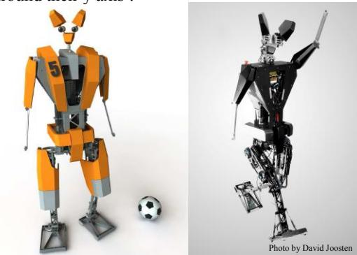
TUlip is a teen sized (1.2m, 18kg) 17 degrees of freedom (DOF) autonomous humanoid robot with 12 electrically actuated joints, see Fig. 1. It has been designed to have a large range of motion around the lower body joints. The hips each have 3 degrees of freedom which allow for 90º about their x and z axis, and more than 180º around their y axis.
N.B. We took the X-Y-Z coordinate plane to be depth, width and height respectively of the robot, e.g. X is from front to back, Y is from head to 'toe' and Z is 'shoulder to shoulder'.
Walking
(Section overview - see subsections below)
Limit Cycle Walking
Our walking research focuses on energy-efficient and human-like walking motions. This research is based on earlier research on Passive Dynamic Walking [8], which featured passive legged mechanisms that could walk down a shallow slope with no actuation or control. Their motion was naturally stable without requiring active control. Their energetic cost for walking is less than 0.1 Joules per unit of weight per meter traveled. Adding weak actuation [1,6] to the concept of Passive Dynamic Walking led to prototypes that walked on level ground with similar low energy use, in the same range as human walking but ten times more efficient [1] than the Honda Asimo [9]. Asimo and most other currently existing walking robots use high-bandwidth position control in all of the joints in order to accurately follow pre-defined trajectories. Position control, however, does not fit well with the purpose of walking. It does not matter much what the exact knee angle is, for example, as long as it bends sufficiently during the swing phase. We realized that we can trade position accuracy for efficiency by using force control. As a result, we could not design our robot with standard servo motors, but we had to design our own actuation system.
Joint Actuation
TUlip uses Series Elastic Actuation [10]; a spring is placed between the load and the motor (i.e., in the steel cable connecting the motor with the joint). The rotational difference between the motor and the joint (measured with two encoders) determines the spring expansion and thus the actuation torque.
The joints actuated trough series elastic actuation are the Ry (pitch rotation) of the knee, ankle and hip as well as the Rz (roll) of the ankle. In addition to allowing good force control, an additional advantage of series elastic actuation is that it increases shock tolerance for the motor gearbox.
All together, the robot uses 10 Maxon DC motors of type RE30, three of which are located in each hip (Rx, Ry and Rz), one for each ankle, one for each knee and two Maxon type RE25 DC motors for the shoulders. All the motors have optical encoders.
Electronics
(Section overview - see subsections below)
Amplifiers and sensors
The MAXON motors are powered by ELMO WHISTLE 5/60 and 20/100 digital servo amplifiers which are PWM controlled by a PC104 stack plus a Mesa 4I65 Anything-I/O PCB running the Mesa Hostmot12 software on its onboard Xilinx Spartan-II 200k gate FPGA.
The hip, knee and ankle of both legs have 8 additional SCANCON encoders, which are connected to a second 4I65 PCB running a modified version of the Hostmot12 software on its FPGA. Each foot has four Tekscan Flexiforce pressure sensors in order to determine the center of pressure. The force sensors are interfaced using custom-designed ARM7 board, which is used to linearize the sensor's signals and give pressure and position values to the central controller. Furthermore the ARM7 board is equipped with a STMicroelectronics 3D accelerometer used to determine the precise moment of impact of the foot with the floor or the ball. The foot electronics are interfaced to the main control system using a standard USB interface. These signals will be used for stability control together with an Xsens Mti sensor in the upper body.
Control System
Both Mesa 4I65 PCB's and a 5VDC power supply are mounted on the PC104-Plus stack of an EPIC format sized Diamond Poseidon single board computer with a 1GHz Via Eden CPU. The Poseidon PCB also contains 512MB SDRAM, a 4GB Flashdisk and digital and analog I/O. All encoders are connected to a custom designed Encoder connection PCB, while the 12 Whistle servo amps are mounted on 2 custom designed PCB's. To monitor the battery status we have a PCB with battery monitor IC's that automatically switch off the power to prevent excessive discharge of the batteries.
The computer is powered by a Kokam 3-cell 6 Ah LiPo battery, the motors by a separate 8 cell 3.3 Ah LiPo battery. Uptime with this setup should be about 30 minutes.
On the Poseidon we run an Xenomai Linux build on Debian as RTOS platform. Linux drivers for the Mesa4I65 Anything-IO boards have been developed by the Embedded Systems group of the UT.
Software
(Section overview - see subsections below)
Overview
The software system controlling TUlip is based on the concept of independent modules each performing their own specific task. The software architecture is based on the RoboFrame framework developed by the German Robocup team of Darmstadt Technical University [11]. This is a C++ based framework that provides a number of services to robot control applications such as module management, timers, intra and inter-process communication, a GUI template, and wireless UDP communication using 802.11g hardware.
As the current TUlip robots are partly based on principles learned from the TU Delft Flame biped some of the software design is similar. Flame uses a motion control based on hierarchical state machines. The state machines aid efficient concurrent design and implementation of the various behaviors used to control the robot.
To offer a particular service to the rest of the application a module needs to publish a well defined interface consisting of messages that can be transmitted using the communication facilities the RoboFrame supplies. An example of such an interface is the set of commands the motion module accepts from the rest of the system; each message indicates a particular type of motion with optionally a list of parameters.
The main modules present in the Dutch Robotics robots are Motion, Vision, Communications, World Model and Strategy. All these modules run on the Poseidon SBC.
Motion
The RoboFrame has no native software support for real-time platforms required for motion control. Therefore, this part of the system is implemented outside of the RoboFrame application, but still on the Poseidon SBC. There are no dedicated hardware control systems. For operational reliability, the motion control is implemented as a separate real-time process interfacing with an adapter module that is running inside the RoboFrame application. This RoboFrame module accepts commands from other modules (strategy) and relays those to the real-time process running the actual motion control. Sensor data from the motion controller is sent back through the adapter for use by the rest of the modules. This prevents disastrous motor behavior when a non real-time application (vision and behavior modules) crashes.
World Model
The world model is responsible for maintaining information about the state of the external world. It receives sensor data from both the motion and vision modules, as well as information through the communications module. All other modules that need information on the robot state (attitude, position, viewing direction) depend on the world model. Strategy relies on the world model for performing autonomous control of the robots actions in the soccer field.
Vision
(Section overview - see subsections below)
Head
On the head two Virtual Cogs VC21CC1 Camera Cog cameras are used with a Virtual Cogs OV9653 optical sensor each. Both sensors are connected to a Virtual Cogs VCMX212 single board CPU with dimensions of 44 by 50 mm. The visuals are processed in a resolution of 640x480 at 30 fps. The single board CPUs are connected to the Poseidon computer through a USB connection.
The head is connected to the body by three Dynamixel RX-28 motors which give a three degree of freedom mount. The head neck combination is about 15 cm of height. Ranges of motion are 180 degrees for panning, 100 degrees for tilting and a forward-backward stroke of about 4 cm.
Control
The stabilization algorithm takes orientation and acceleration data from the Xsens and counteracts head rotations and displacements. The saccade algorithm points the camera at salient features in the environment. The most challenging part here is the detection, selection and tracking in time of these features. The pursuit algorithm, finally, smoothly tracks a selected salient feature if it is moving.
Image Processing
The task of image processing is to determine the location of features in the world from the images produced by the cameras. Interesting features in a Robocup game are ball, goal, opponents, field markers and such. The vision software proceeds basically as follows:
- Apply lens distortion correction and epipolar alignment to the images
- Segment by color
- Detect features in segmented image
- Perform sparse stereovision on color-segmented features
- Combine many different hints gathered from the images to determine position in the world
In addition, there is the possibility of dense stereovision. This allows for instance the detection of the ground plane. This ground plan can be used to provide on-line color calibration information for adapting to varying light conditions.
References
[1] S. H. Collins, A. Ruina, R. L. Tedrake, M. Wisse, "Efficient bipedal robots based on passive-dynamic walkers", Science (18 February 2005), V307, p.p.: 1082-1085. [2] M. Wisse, G. Feliksdal, J. van Frankenhuyzen, B. Moyer, "Passive-based Walking Robot", IEEE Robotics & Automation Magazine (2007), V14(2), p.p.: 52-62 [3] G. van Oort and S. Stramigioli, "Using time-reversal symmetry for stabilizing a simple 3D walker model" in: Robotics and Automation, 2007 IEEE International Conference on, IEEE RAS, Rome, pages 4673-4678, 2007 [4] E.C. Dertien G. van Oort and S. Stramigioli, "Realisation of an Energy Efficient Walking Robot" in: Proceedings of the 2006 IEEE International Conference on Robotics and Automation, 2006 [5] P.H.M. Daemen, "ZMP based control in 3D passive dynamic walking", MSc. report, UTwente, January 2007. [6] E.C. Dertien "Dynamic walking with Dribbel", IEEE robotics and automation magazine, 13 (3). pp. 118-121. ISSN 1070-9932 (2006) [7] D. G. E. Hobbelen, M. Wisse, "Limit Cycle Walking", in book "Humanoid Robots; humanlike machines", edited by M. Hackel, 2007, published by Advanced Robotic Systems International, Vienna. Ch.14, p.p.: 277-294, ISBN: 978-3-902613-07-3. [8] T. McGeer. Passive dynamic walking. Intern. J. Robot. Res., 9(2):62–82, April 1990. [9] Y. Sakagami, R. Watanabe, C. Aoyama, S. Matsunaga, N. Higaki, and M. Fujita. The intelligent asimo: System overview and integration. In Proc., Int. Conf. on Intelligent Robots and Systems, pages 2478–2483, 2002. [10] G. Pratt and M. Williamson. Series elastic actuators. In Proc., Int. Conf. on Intelligent Robots and Systems, Pittsburgh, PA, 1995. [11] M. Friedmann, J. Kiener, S. Petters, D. Thomas, and O. von Stryk, "Modular software architecture for teams of cooperating, heterogeneous robots," in Robotics and Biomimetics, 2006. ROBIO '06. IEEE International Conference on, 2006, pp. 613-618.