Persian Gulf Robotics 2009 Teen-Size Team Description
Atefeh Ahmadi, Sayed Majid Momeni, Mohsen Fouladfar, Vahid Mohammadi, Jalil Jalili, Sadjad Pour Memar
Computer Engineering; Mechanical Engineering; Electrical Engineering
Abstract This document describes the specifications and functions of the humanoid Robot which is developed by Persian Gulf Team as a platform for research .we won the first place at Iran Open2008 Competitions .The robot will attend in TeenSize League of Robocup competitions in 2009, Graz, Austria.
1 Introduction
The Persian Gulf Humanoid Robot Project has been running at Khorasgan University and sponsored by Bonyad Shahid Isfahan organization, Iran, since 2006. Since then we have started the humanoid robot project, and now we focus our research interests in mechanisms of humanoid robot, bipedal locomotion, robot vision, self-localization and multi-robot cooperation.
2 The Robot
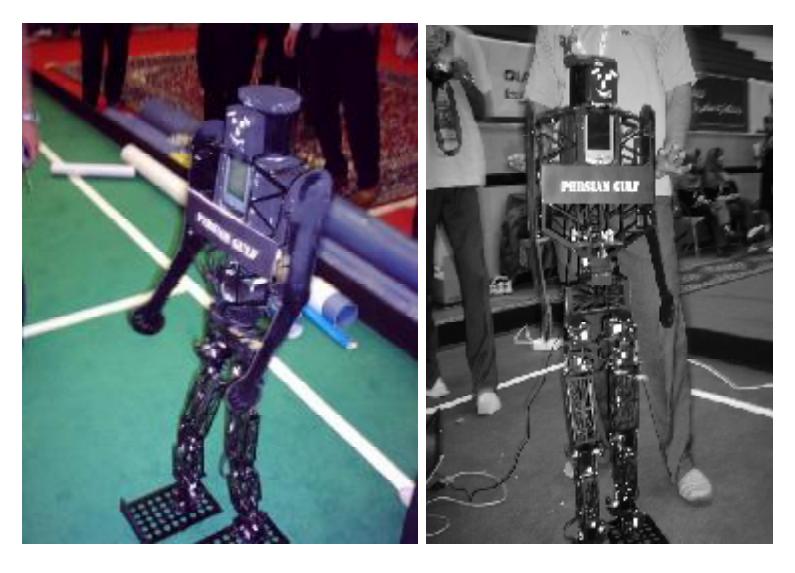
Table 2.1 - Specification of robot
| Team Name | ||
|---|---|---|
| Actuators | Dynamixel RX 64 & DX 117& RX-28 | |
| Joint DoF | DOF | |
| Head | Yaw×1 | |
| Shoulder | Pitch×2 | |
| DOFs | Hip | Roll×2 |
| Yaw×2 | ||
| Pitch×2 | ||
| Knee | Pitch×2 | |
| Ankle | Roll×2 Pitch×2 Total 15 | |
| Height(mm) | 1130 | |
| Computing Units | HP iPAQ hx2790 Pocket PC – CM2+ Processor Board | |
| Camera | HP iPAQ PhotoSmart Mobile Camera | |
| Walking Speed (m/sec) | 0.2 m/s | |
| Weight (kg) | 3.1 kg |
2.1 Mechanical Design
Fig. 2.1 shows our newly developed kicking the ball. The robot is 1130mm high and weights 3.1Kg including Pocket PC and batteries. It has 15 DoFs : 3 in each leg,1 in each arm, 1 in the head and 3 in the hip.
Table 2.1.1 - DOFs of robot
| Joint | DoF |
|---|---|
| Head | Yaw×1 |
| Shoulder | Pitch×2 |
| Hip | Roll×2 |
| Yaw×2 | |
| Pitch×2 | |
| Knee | Pitch×2 |
| Ankle | Roll×2 |
| Pitch×2 | |
| Total | 15 |
All the actuators are Robotis RX-64,Robotis DX-117and Robotis RX-28. Table 2.1.2 shows the specification of each actuators.we have used alominum material because it was light, strong, easy to work with and cheap.
Table 2.1.2 - DoFs
| Properties | RX 64 | DX 117 |
|---|---|---|
| Weight(g) | 116 | 66 |
| Gear Reduction Ratio | 1/200 | 192.6 |
| Input Voltage | 18 | 12 |
| Final Max Holding Torque(kgf.cm) | 64 | 28.89 |
| Sec/60degree | 0.162 | 0.172 |
| Manufacturer | Robotis | Robotis |
2.2 Equilibrium Formulas
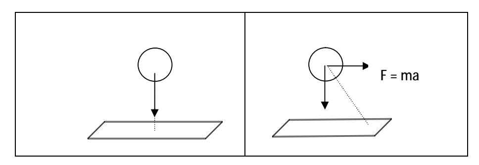
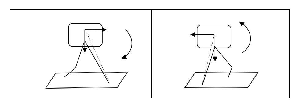
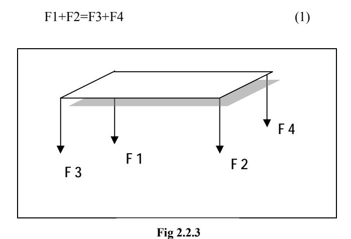
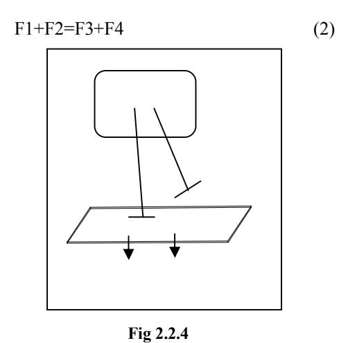
The robot's equilibrium system is divided into two parts: static and dynamic.
The dynamic equilibrium system is been used in this robot. As the robot's equilibrium is not conform with reality, the desired equilibrium is got through received data from sensors. In both kinds of equilibriums the resultant of forces on the whole robot has to be put on the support leg.
3 Electrical Design
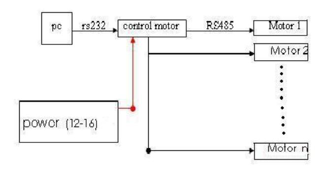
Regarding to the robot's dynamic design, electronic part is divided into two parts :
3.1 Strong Network
Including Actuators, Behaviuor Control and Power.
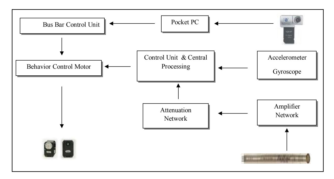
3.2 Control Network
Including Sensors Network and Actuators feedback Network.
4 Vision
The vision module consists of two parts. On the aspect of hardware ,HP PhotoSmart camera is employed as vision sensor. And we have two tasks in the software, object recognition and relative position estimation.
4.1 Vision Sensor
For robot, a camera is used. camera is connected to the Pocket PC via a SD port. And image series of a resolution of 320×240 can be provided in real time by up to 10 frames per second.
4.2 Learning Color Object
In this part we take a photo from playground that contains our desired object ,then evaluation would be done and then it added to the object table . At the end creation of a database of object for knowledge of vision would be accomplished.
4.3 Position estimation
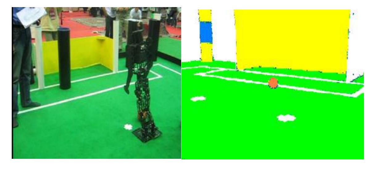
As you know, according to the knowledge base when a pixel's R, G and B can be put in a particular object's R,G and B, that pixel is belongs to that object and we can convert the pixel's details to the object's details and finally we have a picture with 6 colors!
The camera's picture resolution is 240*320 pixels on which decreasing the resolution has to be done, which caused deleting undesired noises and a simpler working area.
In the next step robot's position regarding to the ball and net and penalty point is considered and compared with experimental information saved in a table called lookup table.
References
- MC. Geer ,T, "Passive Dynamic Walking" , The International Journal Research,vol.9, N. 2, pp. 62-82 , Appril 1990
- R. C. Gonzalez, R. E. Woods (Contributor), and R. C. Gonzalez, Digital Image Processing,3rd ed., Addison-Wesley, Reading, MA, 1992.
- Goutsias and L. M. Vincent, Eds., Mathematical Morphology and Its Applications to Image and Signal Processing, Kluwer, Norwell, MA, 2000.
- Allen S. Parseghian. , "Control of a Simulated, Three-Dimensional Bipedal Robot to Initiate Walking, Continue Walking, Rock Side-to-Side, and Balance" , University of California, Berkeley , September 2000 .
- David Prasser. , "Vision Software for a Humanoid Soccer Robot" , The University of Queensland ,19th October, 2001.
- Miyazaki, F., Arimoto,S.: A Control Theoretic Study on Dynamical Biped Locomotion.ASME J. Dyna., Syst., Meas., Contr. 102 (1980) 233-239.
- Furusho, J., Masubuchi, M.: A Theoretically Motivated Reduced Order Model for the Control of Dynamic Biped Locomotion. ASME J. Dyna., Syst., Meas., Contr. 109 (1987) 155-163.
- Pauk, J. H., Chung, H.: ZMP Compensation by On-Line Trajectory Generation for Biped Robots. IEEE International Conference on Systems, Man, and Cybernetics. 4 (1999) 960-965.
- Huang, Q., Li, K., Nakamura, Y.: Humanoid Walk Control with Feedforward Dynamic Pattern and Feedback Sensory Reflection. IEEE International Symposium on Computational intelligence in Robotics and Automation. (2001) 29-34.