Team AcYut – Team Description Paper 2015
Dr. B. K. Rout, Kaustubh Nawade, V. Aditya, Pratyush Kar, Anirudh Bhutani
Center for Robotics and Intelligent Systems; Birla Institute of Technology and Science, Pilani, Rajasthan, India
www.bits-pilani.ac.in · www.acyut.com
Abstract This paper explains the working of our humanoid robots, AcYut, which we intend to use for the RoboCup Humanoid Teen size soccer competition. As per the regulations of the competition, AcYut's structure is designed in accordance with human proportion. It is able to walk utilizing the Linear Inverted Pendulum Model as a default open loop trajectory, and an Inertial Measurement Unit for detecting destabilizations. In order to perceive its environment it is equipped with a fish-eye camera. Image processing and decision making takes place on an Intel i3- 4010U processor.
1. History:
AcYut is a series of humanoid robots developed by the undergraduate students of Birla Institute of Technology and Science, Pilani. The aim of the project is the development of a humanoid robot that has the capabilities of being used in actual applications. Our team made its first humanoid robot, AcYut I, in 2008. AcYut I was India's first indigenously developed humanoid robot. After AcYut I, the team built a stronger, taller and better version of the robot, AcYut II. AcYut II was semi-autonomous and could be operated by use of a controller. The team also developed a third version of the robot, AcYut III, which had superior computing power enabling incorporation of advanced algorithms. Improving upon the design of AcYut III, AcYut IV was developed. AcYut IV was the team first entry to RoboCup in 2011. It managed to reach the third position in the TeenSize Humanoid category. The team has also won other accolades, some of the notable ones being Gold and Silver medals in humanoid Sumo wrestling at RoboGames 2010 and world record for the most weight lifted by a large humanoid (40 CDs) at FIRA 2010, held at Bangalore in September 2010. The team subsequently participated with the new design and humanoid AcYut V, in RoboCup 2013 at Eindhoven, Netherlands where we stood 4th in the humanoid teen size league category.
2. Summary of Progress:
The team has primarily made progress on a software level. The image processing module has been updated to achieve shape based ball and goal post detection to account for the new RoboCup 2015 specifications. The gait generation module now rejects disturbances with a closed loop using the IMU sensor for feedback. The behavior module has been refined to include fail safe mechanisms for the path planning and image process modules such that failure of either of the two will not lead to the robot reaching a motionless state. The electrical circuitry of the robot now includes voltage and current regulation.
3. Mechanical Design:
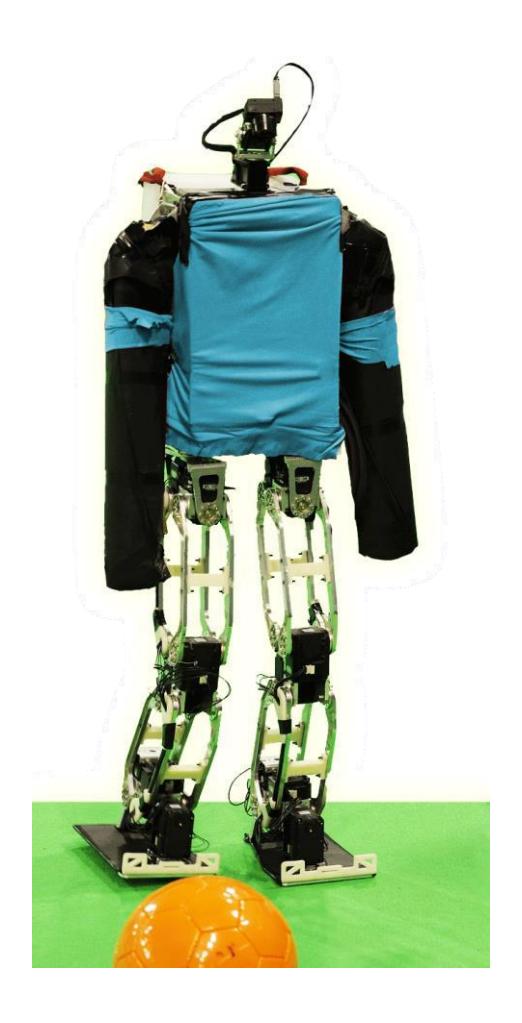
AcYut VII has 23 degrees of freedom distributed as follows: 14 in legs, 8 in arms, 1 in head. Every degree of freedom is actuated by Robotis Dynamixel motors. All brackets of AcYut are made of Aluminum 6061-T6 and are designed to reduce the net weight of the robot while providing adequate strength.
Physical Specifications of the robot are as follows:
- Height: 101 cm 2. Weight: 7.1 kg 3. Walking Speed: 22 cm/s 4. DOFs: 23
5. Actuators:
Robotis EX – 106: 106Kgcm @ 15V in Legs.
Robotis MX – 64: 64Kgcm @ 14.8V Arms, Head and Yaw Rotation of Legs
A degree of freedom has been reduced in the head since the fish-eye lens' wide field of vision makes updown motion of the head redundant. The EX and RX motors are now powered at their lower voltage limit.
4. Electrical Design:
The processing requirements of the humanoid are met by an Intel i3-4010U processor, which is connected to the camera, IMU, and actuators. Wireless communication with the processor has been established. The processor is powered by a Lithium Polymer battery with regulated voltage. The voltage supplied to all motors are likewise regulated to accommodate voltage fluctuations. The IMU is used to localize the robot using yaw angle to determine the present heading, and to stabilize it by detecting disturbances using the roll and pitch angles.
Electrical components in the system are as follows:
- Sensors:
a. Camera: iDS UI-1221LE-C-HQ (752x480 CMOS color)
b. IMU: 9 DOF XSens IMU
Processor: Intel® NUC Kit D34010WYKH (Intel i3-4010U)
Batteries: Lithium Polymer 4 cell batteries
Other: Wireless LAN (IEEE802.11a/b/g), Regulators
5. Software and Algorithms:
[This section contains multiple subsections detailing the robot's software architecture and algorithms]
1. Behavior
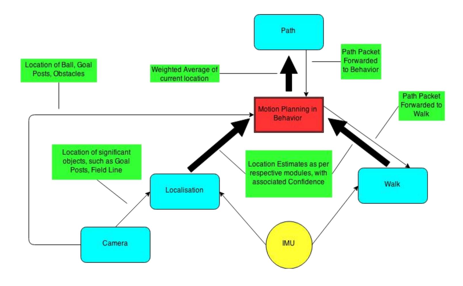
The behavior module is transfers information across different modules and incorporates fail-safe mechanisms to accommodate the crash or inaccuracy of any module. The image processing module may fail to locate the ball or the goal post. In such a scenario, the behavior framework will supply last locations of the same to the path module so that a path can be generated. Since such processes occur on a frame-by-frame basis, errors introduced by such mechanisms are easily corrected later.
Another crucial function of the behavior module is to maintain a current global position of the robot. It achieves this by using a motion model framework which is charted out above. The localization module forwards the present global location with an associated confidence. Similarly, the walk module maintains a constantly updated current position estimate which also has an associated confidence derived from the accuracy of the walk of the robot. This confidence decays exponentially with time, and the model is refreshed whenever the robot localizes with high confidence. In case the localization module reports a low confidence value, the motion model framework looks to the walk position estimate for the current position. In some cases it uses a weighted average of the two. It then forwards the current position to the path planning module.
2. Image Processing
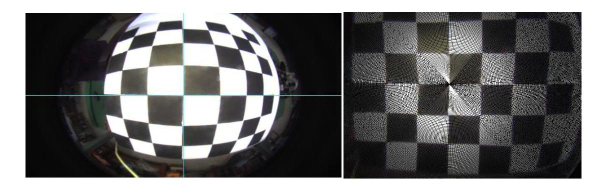
Image processing (IP) corrects the inherent distortion introduced by a fish-eye lens to generate a rectilinear image. Shape-based detection using Genetic Algorithms, and color-based detection using lookup tables is used to identify objects of interest, and their location relative to the robot is computed using Inverse Perspective Mapping.
3. Localization
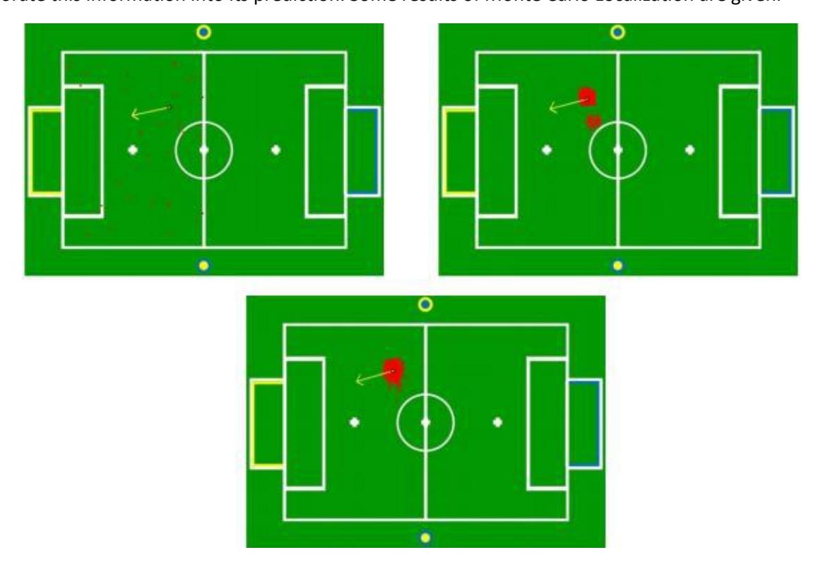
This module enables the robot to determine its own position within the soccer field. Monte Carlo localization is used. Particles for the localization model are randomly chosen within the field area and probability of each particle is calculated based on distance from observed landmarks.
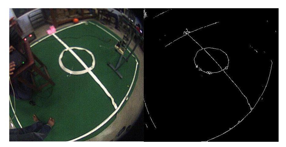
The Localization module serves to identify the global position of the humanoid using landmarks for computing a probability density function associated with the current predicted position. After the detection of field lines was achieved on a fish-eye lens, the Localization module was updated to incorporate this information into its prediction. Some results of Monte Carlo Localization are given.
4. Path Generation
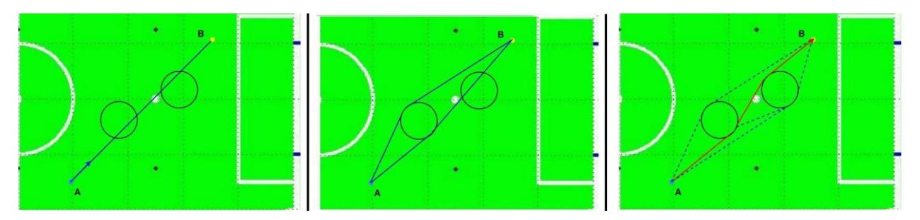
After localization and ball detection have been successfully performed, the path generation module is used to find the best possible path to the ball. For this we use a geometry based approach which provides quick results. Obstacles are modeled as circles and arcs of concentric circles are taken as the shortest route around the obstacles. Shortest distance between two points not blocked by an obstacle is the straight line joining the two points, whereas the cost is decided based on various factors like the time it takes for AcYut to turn in comparison to straight line walk.
5. Gait generation and balance
The gait generation module maintains the Center of Mass on a Linear Inverted Pendulum trajectory in the sagittal and lateral axes. An IMU sensor and joint angle sensors are used to detect deviations from the nominal trajectory. Minor disturbances are corrected using a PI controller for disturbance rejection. For larger deviations a push recovery framework has been developed based on the concept of capture points. The robot calculates new footstep positions of the free leg to allow the center of mass to return to the default trajectory. This computation is performed by conserving the energy of the CoM on LIPM trajectory. The posture of the robot has been modified so as to lower the knees and separate the legs outward. This modification allows the robot to reach larger step lengths and consequently a higher velocity.
6. Conclusion:
AcYut VII is an autonomous humanoid robot. In this paper we have mentioned the specifications and working of AcYut VII and details about its control system, image processing, localization, path planning, decision making and gait generation. We have also included the latest progress made in the technology and software in the past year (2014-2015).
Team AcYut intends to participate in the Humanoid Teen Size Robot Soccer league in RoboCup-2015, to be held in Hefei, China and put will put forth its best efforts for the same. A person from the team with sufficient knowledge of the rules shall also be made available to be used as a referee.
References
- Kajita et al. The Linear Inverted Pendulum Mode - A simple modeling for a biped walking pattern generation in IEEE International Conference on Robotics and Automation, Maui Hawaii, USA – November 2001
- Sven Behnke. Online Trajectory Generation for Omnidirectional Biped Walking in IEEE International Conference on Robotics and Automation, Orlando, Florida - May 2006
- Hannes Schulz et al. Line Structure-based Localization for Soccer Robot. IEEE-RAS Intl. Conf. On Humanoid Robots (Humanoids 2009), Paris (France), 2009
- Jen-Shiun Chiang et al. An Efficient Object Recognition and Self-Localization System for Humanoid Soccer Robot. SICE Annual Conference 2010
- Nizami Gasilov et al. Two stage shortest path algorithm for solving optimal obstacle avoidance problem. IETE Journal of Research, May – June 2011
- J. Pratt, J. Carff, S. Drakunov, and A. Goswami, "Capture point: A step toward humanoid push recovery," in 6th IEEE-RAS International Conference on Humanoid Robots, December 2006, pp. 200– 207.