AMN United Humanoid Teen Size Team Description Paper
Amirhossein Hosseinmemar, Meng Cheng Lau, John Anderson, Chi Fung Lun, Ziang Wang, Sourosh Sadeghnejad, Amirali Setayeshi, Jacky Baltes
Autonomous Agents Laboratory Department of Computer Science University of Manitoba Winnipeg, Manitoba, R3T 2N2, Canada; Bio-Inspired System Design Laboratory Amirkabir University of Technology (Tehran Polytechnic) No. 424 Hafez Ave., Tehran, Iran, PO Box 15875-4413; Department of Electrical Engineering National Taiwan Normal University Taipei, Taiwan
http://aalab.cs.umanitoba.ca/ · http://autman.aut.ac.ir · http://www.ee.ntnu.edu.tw/
Abstract This paper describes the 2018 AMN United Teen Size Team, a team jointly developed by three universities: Amirkabir University of Technology (Tehran Polytechnic) of Iran, The University of Manitoba, Canada, and National Taiwan Normal University, Taiwan. This extends the partnership between Amirkabir and Manitoba (AUTMan) that goes back to 2013. We provide a brief history of our team's past performance, and describe current hardware and software. We then describe current research in terms of push recovery and active balancing.
Introduction
Encouraging joint research in AI and robotics is an important goal of the RoboCup Humanoid league, to counter the difficult entry level bar as teams become larger to meet the ultimate goal of an 11 member team that can play against humans [1]. Even with smaller numbers of robots, it is not easy in teen and adult size leagues for a single university to gather the resources necessary in terms of people and hardware to make a strong team. Working with multiple partners has important challenges, such as compatibility in communication, sharing facilities for important components such as localization and vision among different robotic hardware, and managing the development process. Solving these problems results not only in stronger teams, but in better overall development methodologies that transfer to other domains.
We have been developing joint Kid Size and Teen Size RoboCup teams between the Bioinspired System Design Laboratory of the Amirkabir University of Technology, Iran and the Autonomous Agents Laboratory at the University of Manitoba, Canada (AUTMan) since 2013. Success in a team requires addressing all elements of the challenge problem of soccer: strong vision, localization, control, and teamwork. The fact that our teams are based on a geographically distant partnership means that we also have to address important issues of shared development over great distances and sometimes only seeing the hardware together for the first time in a competition setting. This requires strong communication between groups, the use of simulation software as well as hardware, and forward planning so that code modifications can be made quickly when problems arise during competitions or when unexpected conditions occur. It is also advantageous to do joint test runs in open competitions prior to RoboCup (e.g. AUTCup, Iran Open).
This year, Amirkabir and Manitoba are joined by National Taiwan Normal University, resulting in joint work between three very distant partners. This paper describes our joint work on the 2018 AMN United Teen Size Team. We begin by reviewing past performance, then describe our robot hardware and software. We have a particular interest in the technical challenges that form a part of the Humanoid League, and so in terms of current research we also describe recent work on active balancing and push recovery.
Previous Achievements and Current Development
Our prior AUTMan teams have a strong history of success in previous competitions. In RoboCup 2015 in Hefei, our team placed third in the Teen Size League, and we repeated this at RoboCup 2016 in Leipzig, and at RoboCup 2017 in Nagoya. We have also performed strongly in the technical challenges for the RoboCup Humanoid League, placing first at RoboCup 2014 in Joao Pessoa (along with Team Nimbro from Bonn Germany), second at RoboCup 2015 (along with the joint WF Wolves and Taura Bots team), first at the 2015 Iran Open, first at RoboCup 2016, and third at RoboCup 2017. The joint members have also published actively both in RoboCup Symposia (e.g. [2–5] as well as humanoid robotic conferences and journals (e.g [6, 7, 1]).
For 2018, we are focussing on three areas of work. The first is the introduction of improved hardware, based on the humanoid league long term road map. The second is improving our software, both in terms of our overall architectural framework (we employ ROS [8] for modularity and sharing between partners) and our simulation models to allow testing and development without wear and tear on the robot. The latter is a vital development tool, since the wear and damage to physical servos when attempting tasks such as jumping can be severe. Finally, we are working on improved active balancing and push recovery.
Hardware
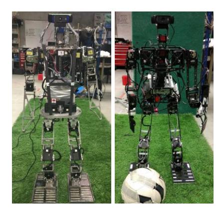
For 2018, our robots will consist of two different platforms. The first of these is hardware we have used previously: Polaris (Fig. 1, left) is a is a 94 cm humanoid robot with 20 degrees of freedom (DOF), weighing 7.5 kilograms, based on Dynamixel servos from Robotis. All the servos use the TTL serial communication protocol with three pins that share one line for sending and receiving data. Each hip can rotate in the sagittal, frontal and transversal planes. There are 6 MX-106 servos in each leg (Hip transversal, Hip sagittal, Hip frontal, Knee sagittal, Ankle frontal, and Ankle sagittal). The two arms rotate in the sagittal and frontal planes, and each arm has 3 MX-64 servos (Shoulder sagittal, Shoulder frontal, and Elbow sagittal), upgraded from MX-28 servos. The neck is made up of 2 MX-28 servos and rotates in the sagittal and transversal planes, moving an attached Logitech C920 webcam. A GIGABYTE BRIX Mini PC is used for computation, with a 2.3GHz Intel Core i3-6100U, 4GB RAM, and 120GB SSD.
For 2018 we are introducing two robots based on a new design, shown on the right side of Fig. 1. These have 22 DOF, structured similarly to Polaris, but with two degrees of freedom added to the torso: Torso transversal and Torso sagittal (MX-106 servos). These additional DOF support more advanced motion planning by extending the reachable workspace of the robot. These units carry a QuanMax QutePC 3001 for computation, with 1.1GHz Celeron Dual Core, 2 GB DDR3 RAM and 32GB SSD.
All robots use a U2D2 communication converter that enables direct control to the servos. This unit is smaller than the USB2Dynamixel used previously, and has mount holes to make it easier to install on robots. All robots also have PhidgetSpatial Precision 3/3/3 High Resolution IMUs (updated from the previous InvenSense MPU-6050 ). These consist of a 3-axis accelerometer, gyroscope and compass, and provide higher resolution readings compared to the earlier IMU model.
Software: Main Components
Our software framework is based on that used in our 2017 team (AUTMan [9]), with improvements to organization and specific modules. Our framework is based on ROS [8], which manages a structured communication layer between major system components and robot servos. Central to our framework is the actuator controller, which interacts directly with all robot servos by sending instructions through the U2D2 communication converter. This provides custom ROS services at both high (e.g. walking) and low (e.g. servo status) levels. With these custom ROS services, we are able to simplify frequently-performed tasks. For example, tuning walking engine parameters is necessary to adapt to different tasks and walking surfaces, and the ROS walking service can reconfigure these through run time messages.
One of the main tasks this year has been to refactor all of our code to eliminate specialized elements and exceptions, isolate and parameterize components, and develop common shared services. For example, previously there was tight coupling between code for vision and code for neck control, since the neck is used mainly for vision tracking, resulting in some servos being treated distinctly from others. Now our vision module is cleanly separated from the actuator controller so that the output of vision is used by the actuator controller distinctly, and motion is treated more generally (e.g. vision tracking could now involve the new torso servos as well as the neck transparently). Another effect of this refactoring has been to greatly speed code modification at competition time, with a greater reliance on parameter and service call changes rather than low level code.
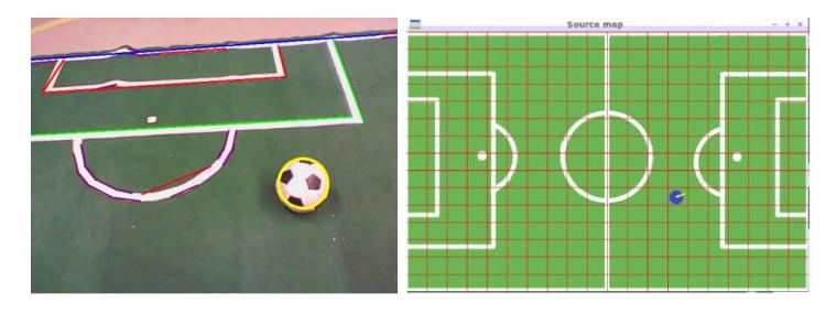
In terms of improving particular components, we have concentrated this year on improving vision, which in turn supports better localization and more accurate motion planning. We upgraded our vision library to OpenCV 3.2 to provide additional image processing algorithms. Our improved vision module is intended to better detect selected features in the soccer field such as goal lines and baselines. The binary descriptors for line extraction in OpenCV are mainly based on the line segment detection algorithm introduced by Gioi et al. [10]. We found this to produce significant noise, and so we implemented an improved line segment detector that uses a corner detector and various geometric approaches to eliminate noise such as insignificant line segments. This has improved vision, and in turn the accuracy of particle filter based localization (Fig. 2).
Simulation Modeling
Simulation is an important tool for a team such as ours, with geographically distributed partners and multiple hardware types. Not all hardware can be available at all locations at all times, so accurate models must be available for testing common code. Moreover, as the boundaries in technical challenges get pushed further and further each year by the RoboCup Humanoid League, such detailed simulations become a crucial part of the development process. Research on tasks such as Jumping and push recovery would result in many broken servos and unacceptable wear on equipment if each and every test had to be done on a physical robot. Simulation also lets us integrate new undergraduates into our research program: they can gradually improve their skills and contributions without the concern of damaging equipment.
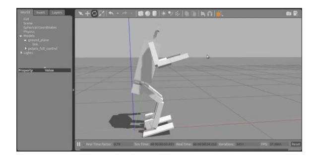
This year we have redeveloped detailed simulation models of our robots for Gazebo (a 3D dynamic simulator). This allows much more detailed modeling than was available previously. Each simulated robot has the exact weight and size of body components, models of individual servos to the same resolution as physical Dynamixel servos, and models of all sensors. As an example, Fig. 3 shows our model of Polaris in the middle of a controlled jump.
In order to visualize the robot's sensory feedback, we employ Rviz, a ROS 3D visualizer framework. In competitions such as RoboCup, every second counts and sometimes there is not enough time to connect extra devices to debug the robot's code on the fly. It also accelerates testing and debugging code: with Rviz we can see what the robot sees with its camera when looking at the ball, for example, and fix problems in Rviz without holding the physical robot and ball. These may seem like small things, but they multiply with teen size and adult size robots, especially for teams with a small number of human personnel.
Push Recovery
One of our main research focuses in recent years has been on active balancing and push recovery. Push recovery is especially challenging when working with robots that have relatively inexpensive servos, since these damage more easily and have lower torque than more expensive alternatives. We currently use a closed-loop control methodology which takes as input the readings from the IMU, and in turn makes alterations to parameters in the robot's walking engine when a fall is detected. These alterations are based on the centroidal moment pivot (CMP) [11] approach, which alter the hips and ankles.
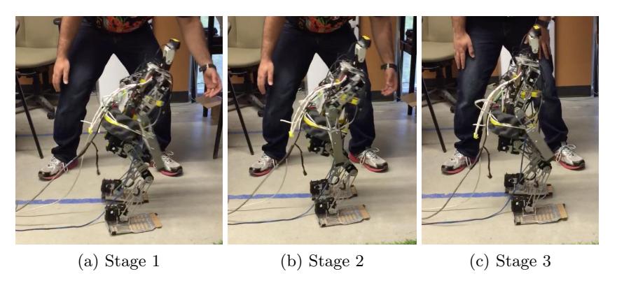
The three phases of our approach are illustrated in Fig. 4. In Stage 1, the robot is pushed at a point in its walking gait on a concrete floor, and must recognize that it is in a falling state. Stage 2 represents a brief window in which the robot can calculate a reaction to the push by calculating control changes based on the angular velocity and the linear velocity of the robot's torso. Stage 3 illustrates recovery, where these control changes alter parameters in the robot's walking engine, which in turn adjust servos and prevent the fall.
In Stage 1, the controller must detect a falling state based in IMU readings. To support a quick response, we discretize IMU output values. We categorize angular velocity in 50◦/s intervals, allowing a definition of constant values for light, medium and strong pushes. This interval was chosen based on a series of walk tests to find the maximum angular velocity the robot encounters while using different walking parameters. We also experimented with linear velocity thresholds by hitting the robot with a weight approximately a quarter of its body weight, and alternatively defined light, medium, and strong pushes as achieving linear velocities of 0.9 m/s, 1.2 m/s and 1.4 m/s, respectively. Using these definitions, we collect 1000 readings per second from the IMU, and use these to continually check if the robot is in a stable state (0 m/s > linear velocity ≤ 0.2 m/s, with this range necessary to deal with sensor noise), or when it is in a falling state by exceeding the stated angular or linear velocity thresholds for light, medium, or strong pushes.
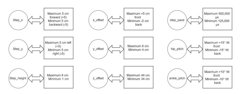
In the short window between detecting a falling state and when the fall would be irreversible (Stage 2), the robot must make a response. Because we know which threshold (light, medium, or strong) has been exceeded we can make a fast response look-up. Our controller produces nine outputs used to alter parameters in the walking engine by modifying hip and/or ankle positions (Fig. 5, showing with minimum and maximum values for each). Step-x is the step length on the x-axis of the robot frame (forward-backward). Step-y is the step length on the y-axis of the robot frame (left-right). Step-height is the foot height from the ground of each step. The x-offset is the offset distance of the feet from the origin/centre of the robot (centre point of the torso) on x-axis. Y-offset is the offset distance on the y-axis from the center of the torso to each foot. Z-offset is the current height of the robot, i.e. standing fully vs. at a crouch. Step-pace is the time it takes to make a single step, while hip-pitch and ankle-pitch affect the lateral motion at the hip and ankles respectively.
The controller will supply values for all nine parameters based on the strength and direction of the push that has been recognized, and each of these is an intended offset value for the current robot pose. Thus, values of 0 represent no change. For example, after a light push on the right side the robot will detect a fall to the left, and the controller will modify the step-y value by 2 cm and the step-pace value by 0.5 per second, leaving all other values unchanged. These values and their mapping to discretized angular and linear velocities (fall states) have been tuned over several years of competitions as well as testing the robot specifically under push recovery conditions. In addition to push recovery, they have proven to be a very fast method of to changing conditions (e.g. carpet vs. solid surfaces).
The supplied control values then change the parameters to the walking engine (Stage 3), and servos are altered to correct for the original disturbance. In controlled evaluations based on prior RoboCup Humanoid League technical challenges, we have found this to be very successful for light and medium pushes. To better handle strong pushes, we are currently working on moving from CMP to a capture steps [12] approach, where the robot takes one or more steps to counter an external force, and using reinforcement learning and deep reinforcement learning to learn appropriate discretizations and parameter settings.
Discussion
This paper has described the work performed by members of team AMN United for our entry to the 2018 RoboCup Humanoid League (Teen Size). We have discussed our hardware and software improvements, as well as work on simulation models and push recovery and active balancing. This will be the fourth year of competition (previously AUTMan) and the first with our new partners at NTNU. We look forward to continuing to expand our joint research. The reader is directed to additional pictures and videos available at our respective websites for further information on past performance of our team entries.
References
- Gerndt, R., Seifert, D., Baltes, J., Sadeghnejad, S., Behnke, S.: Humanoid robots in soccer: Robots versus humans in robocup 2050. IEEE Robotics Automation Magazine 22(3) (Sept 2015) 147–154
- Shafei, H., Sadeghnejad, S., Bahrami, M., Baltes, J.: A comparative study and development of a passive robot with improved stability. In Bianchi, R., Akin, H.L., Ramamoorthy, S., Sugiura, K., eds.: RoboCup 2014: Robot World Cup XVIII, Joao Pessoa, Brazil (July 2014)
- Nagy, G., Baltes, J., Winton, A., Anderson, J.: An event-driven operating system for servomotor control. In Bianchi, R., Akin, H.L., Ramamoorthy, S., Sugiura, K., eds.: RoboCup 2014: Robot World Cup XVIII, Joao Pessoa, Brazil (July 2014)
- Baltes, J., Sadeghnejad, S., Seifert, D., Behnke, S.: Robocup humanoid league rule developments 20022014 and future perspectives. In Bianchi, R., Akin, H.L., Ramamoorthy, S., Sugiura, K., eds.: RoboCup 2014: Robot World Cup XVIII, Joao Pessoa, Brazil (July 2014)
- Javadi, M., Azar, S.M., Azami, S., Ghidary, S.S., Sadeghnejad, S., Baltes, J.: Humanoid robot detection using deep learning: A speed-accuracy tradeoff. In: RoboCup 2017: Robot World Cup XXI, Nagoya, Japan (2017)
- Baltes, J., Bagot, J., Sadeghnejad, S., Anderson, J., Hsu, C.H.: Full-body motion planning for humanoid robots using rapidly exploring random trees. KI - Künstliche Intelligenz (2016) 1–11
- Baltes, J., Tu, K.Y., Sadeghnejad, S., Anderson, J.: Hurocup: competition for multi-event humanoid robot athletes. The Knowledge Engineering Review 32 (2017) 1–14
- Quigley, M., Conley, K., Gerkey, B.P., Faust, J., Foote, T., Leibs, J., Wheeler, R., Ng, A.Y.: Ros: an open-source robot operating system. In: Proceedings of the ICRA-2009 Workshop on Open Source Software, Kobe, Japan (May 2009)
- Ramezani, S., Setayeshi, A., Pourmohammadi, N., Yarahmadi, P., Arvand, A., Fallah, F., Hosseinmemar, A., Morris, K., Lau, M.C., Anderson, J., Baltes, J., Sadeghnejad, S.: 2017 AUTMan humanoid teen size team description paper. https://www.robocuphumanoid.org/hl-2017/teams/ Accesed: 2018-01-12.
- von Gioi, R.G., Jakubowicz, J., Morel, J.M., Randall, G.: LSD: A fast line segment detector with a false detection control. IEEE Trans. PAMI 32(4) (2010) 722–732
- Stephens, B.: Humanoid push recovery. In: Proceedings of Humanoids-2007, Pittsburgh, PA, IEEE (2007) 589–595
- Missura, M., Behnke, S.: Online learning of foot placement for balanced bipedal walking. In: Proceedings of Humanoids-2014, Madrid, Spain (2014) 322–328