EDROM Humanoid Teen Size 2018
Annanda Stephanie, Arthur M. Nonaka, Gabriel R. X. de Araújo, Iago A. Peixoto, Ian Cardoso, Jhonas P. Moura, João V. G. Silva, Jonatas Aguiar, Leandro C. Borges, Lorena Fernandes, Matheus M. Jerônimo, Murilo Venâncio, Nina C. Oliveira, Rogério S. Gonçalves
Universidade Federal de Uberlândia, Faculdade de Engenharia Mecânica, Av. João Naves de Ávila 2121, Bloco 1M Uberlândia, Brazil
www.edromufu.wixsite.com/edromufu
Abstract This paper describes the development of humanoid robots made by team EDROM since their last participation in Robocup 2014. These robots are intended to participate in Robocup 2018 Humanoid Teen Size category. The idea is that the robots can play a football match. The mechanical, software, hardware and scientific achievements are described in this paper.
1 Introduction
EDROM (Equipe de Desenvolvimento em Robótica Móvel) started participating in robots competition in 2010 at CBR (Competição Brasileira de Robótica) and LARC (Latin America Robots Competition). The team already participated two times in the RoboCup, in 2013 and 2014, these were the years with most growth to the team, due to the interaction with other teams [1].
In this paper there are the specifications of the team's robots that will be used in the competition, such as mechanical, hardware, software, improvements and scientific achievements.
2 Overview
The project can be essentially divided in three areas: mechanical structure, hardware and software. Each robot has 20 degrees of freedom using Robotis Dynamixel's actuators [2] connected to an aluminum structure through screws and others nonpermanent connections. However, the team is researching about possible materials to replace aluminum at some points to reduce weight.
The electrical circuit is responsible for ensuring the correct voltage and current for all servomotors, the Intel® NUC [3] computer and its external cooler. There are also some security mechanisms to prevent electrical damage to the components. The camera, IMU sensor and the TTL to USB converter are powered indirectly by the Intel® NUC.
The robot's intelligence is divided in many processes, some of them being multithreaded. The main process starts the communication with the Game Controller and uses its information to decide the robot's next action. The other programs specialize in executing a certain task and the main process starts or stops them according with the robot's current situation.
3 Mechanic Structure
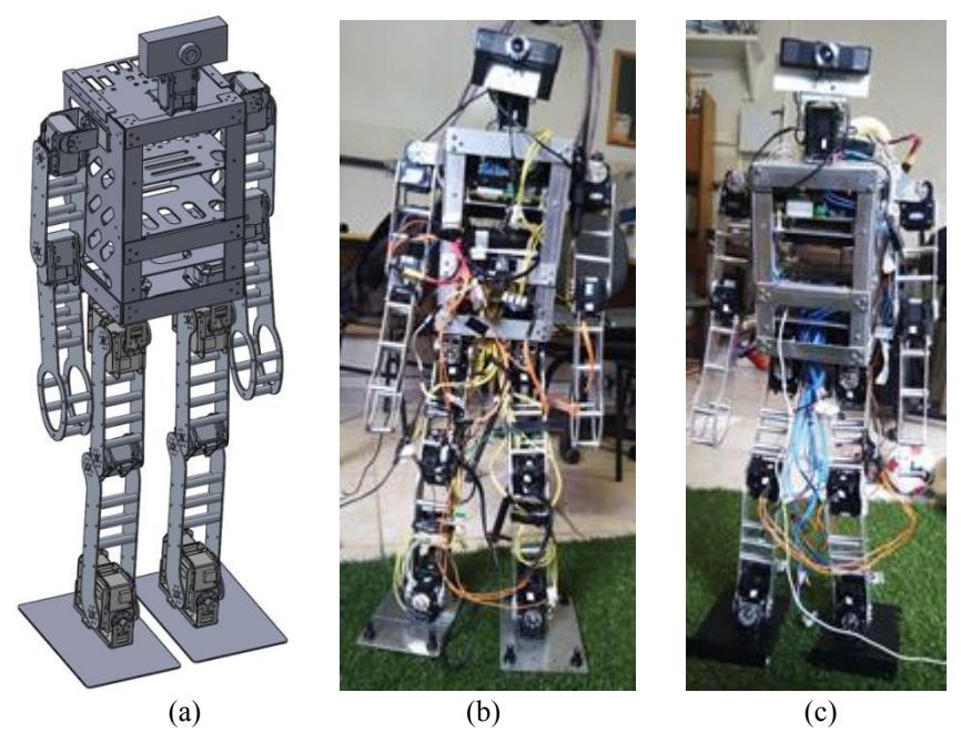
The mechanic structures used were designed so as to fit the rules of the humanoid soccer competition [4] and based from the open source NimbroOP project [5]. For the design and prior analysis of the stiffness and movement, SolidWorks software was used, Fig. 1(a).
We have some alterations in the mechanical project since 2014. The new robots were made mostly in aluminum, the plates have some perforations made in them, so the weight can be lightened, and the electrical system cables can pass through them. The hand was modified to assist the getting-up motion and the feet was modified to acquire the ability to walk on the grass. The built robots are shown in Fig 1.
4 Hardware specifications
The hardware is composed by a few components: Controller; Servomotors; Cables; Batteries; Camera; Cooler; Sensor; A physical interface composed by switch buttons and LEDs; A USB to TTL converter.
The battery connects to a security circuit that is connected to the physical interface, the security circuit is elaborated to prevent overcurrent in the motors and to adjust the voltage. The battery (voltage of 14.8 and 5600mAH) offers 16.6V when fully charged and 14.8V when ending, so, the motors, who operate in the range of 10-14.8V [2], requires the voltage to be lowered to power them properly.
The controller needs a voltage of 20V, so it's also needed to increase the voltage. To do this it's used two DC-DC Step Up and Down module to adjust the voltage needed. The cooler is used to maintain the DC-DC module in the right temperature.
Some of the motors are powered by another battery (11.1, Li-Po 2200mAh) alone without pass through the security circuit because this battery provides 12.6V when fully charged and 11.1 when ending, so it can be used to power the motors without protection.
Besides that, the security circuit also has the switch buttons and the LEDs, they are used to turn the motors the controller on and off and a switch that connect the battery to the circuit when on and disconnect when off. The LEDs are used to inform the state of the switches.
The other components, such as the converter, the camera and the sensors are powered by the intel® NUC via USB cables.
The USB to TTL converter is a project called Mojtaba [6] in homage to the member of the Iran team AUTMan [7]. In short, the team's hardware is an electronic circuit who controls the power provided to the robot and protects it from any problem involving current peaks.
The controller used in the robot is an intel® NUC model 6i3SYK [3].
The servos used on the robot are MX-64 [8] for the two degrees of freedom on the head and the others are MX-106 [2].
The camera is a Genius WideCam F100, with 120 degrees of FOV, low distortion and capability of 30 FPS.
The sensor used is the Phidget Spatial model 1042, it has a Compass 3-Axis (not used), Gyroscope 3-Axis, Accelerometer 3-Axis.
5 Software specifications
The software is composed by the following categories: Vision; Sensor; Movement; Behavior; Strategy; Game Controller.
The goal of the vision process is to locate the field boundaries, ball position, goalpost, landmarks and opponent robots. The implementation is done using the OpenCV library [9] with the "contrib" module which offers many open-source computer vision tools [10].
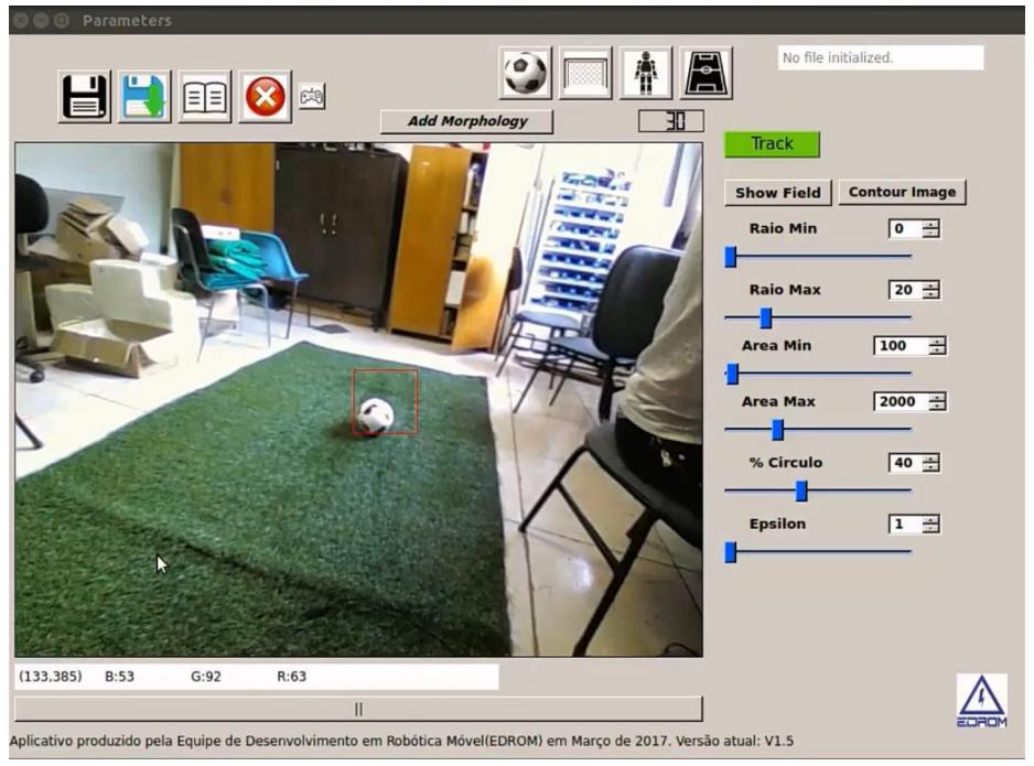
Due to the change of the ball's color in the RoboCup competition it was necessary to implement more sophisticated algorithms to achieve the ball identification. Nowadays there are color filters, morphological filters and tracking tools [11] working altogether to get the ball localization and there still work to be done aiming to improve accuracy. The vision process communicates with the others robot's programs sending the extracted information so that it can be used in the execution of a more intelligent behavior. Figure 2 show the graphic interface developed by EDROM to vision.
6 Research Interest and Scientific achievements
The team's research interests are in the areas that are currently in development such as vision improvement, communication with the motors improvement, structure improvement and others.
In the vision area the team is researching a way to make the robot be able to locate itself in the field alone, it's been tested a way to convert the lines on the field into graphs and compare it to a database who will contain various graphs correlated with a position on the field and by interpolation it it's aimed to obtain the approximate location of the robot.
In the mechanical area it's been researched a way to reduce the weight of the robot to make it easier to execute the movements needed.
In the electric area is there a need to power the motors properly because due to the DC-DC module the motors are not receiving enough current, the module only permits the passage of 10A and each motor can use up to 6.3A when using its maximum torque.
The EDROM team is working in the impedance control that is widely explained in Hogan (1985) [14]. The main idea of this method is to relate the manipulator variables, such as end-point position and force rather than just control these variables alone. In this regard, the impedance control will be analyzed to make the generated walking trajectory suitable with the ground stiffness.
The simplest impedance equation for a single actuator can be described as follows:
$$\tau = K(\theta - \theta_{ref}) + B(\dot{\theta} - \dot{\theta}_{ref}) \tag{1}$$
Where the variables and are related to the desired stiffness and damping for the manipulators respectively. The motor`s angular rotation, and angular velocity are described by and ̇, and the desired position and velocity are respectively ̇ and ̇ . The torque is computed by the right side of the Eq. 1 and it is applied as an input for the servo motor.
The equation (1) indicates a different outlook of the PD controller, in which the gains and are equivalents to and . Once the MX Dynamixel servos have an internal PID controller, the impedance behavior can be defined by setting the integrative gain to zero, and changing the and variables according the desired response when the robot hits the ground.
Although suiting the proportional and derivative gain according to the ground characteristics seems to be feasible by only changing the internal PD gains of the servomotor, this transition may cause undesirable behaviors when tracking a specific trajectory. For this reason, it was added to the system a feedforward action for compensating unwanted effects, mainly the low-pass effect when the servo proportional gain is reduced to provide smoother impacts between feet and ground. This effect is pointed out by Missura (2016) [15], and the applied feedforward compensation follows the same idea from Schwarz and Behnke (2013) [16], in which the MX 106 is modeled as a DC motor considering both the friction in the gear transmission and the internal PID system. The mathematical model is fitted to the data generated from a reference trajectory.
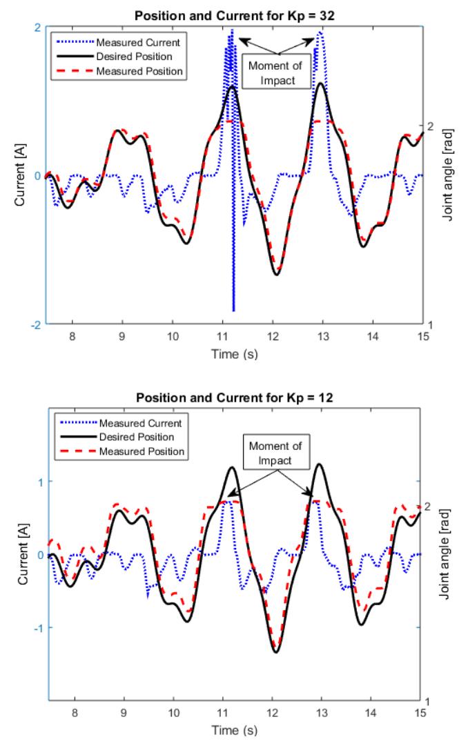
Figure 3 shows a comparison between the factory default gain proportional value (left figure with = 32), and a reduced gain (right figure with = 12) with feedforward action. Both tests were based on tracking a specified trajectory, and there were two moments with impacts as indicted in Figure 3. It is clear that a reduced gain provides smaller current peaks when the system suffers impacts. Moreover, analyzing the RMS error for the position, it was concluded the trajectory tracking follows the desired path with an acceptable tolerance.
Therefore, changing the impedance characteristics of the overall humanoid robot seems to be both feasible and beneficial for the walking movement, since the feedforward action allows to keep an acceptable trajectory tracking even for small values, besides, it provides a possibility for adapting to the ground stuffiness and, at the same time, it may save energy when the robot hits the floor.
7 Conclusions
This paper refers to the steps used by the team EDROM to build the two robots that are planned to compete in the RoboCup Humanoid Teen Size Soccer Competition in 2018.
The project is not in the final version, there are plans to optimize a few areas to have a more agile and enhance its performance. We want implement the impedance control in the humanoid robots until the RoboCup 2018.
The EDROM's team commitment of participating in the RoboCup 2018 Humanoid League competition, also that we will make a person with sufficient knowledge of the rules available as referee during the competition.
8 Acknowledgements
This research has been partially supported by the FAPEMIG, CNPq, CAPES, UFU and FEMEC.
References
- EDROM < http://edromufu.wixsite.com/edromufu >
- Dynamixel MX-106 Robot Actuator < http://www.trossenrobotics.com/p/mx-106tdynamixel-robot-servo.aspx>
- Intel® NUC kit NUC6i3SYK < https://www.intel.com/content/www/us/en/products/boardskits/nuc/kits/nuc6i3syk.html >
- < http://www.robocuphumanoid.org/wp-content/uploads/RCHL-2017-final-2.pdf > "RoboCup", 2017. ROBOCUP SOCCER HUMONOID LEAGUE. RoboCup Soccer Humanoid League Rules 2017 competition.
- < http://www.nimbro.net/OP/ >
- Mojtaba's git < https://github.com/leoxbox >
- AUTMan team < http://autman.aut.ac.ir/ >
- Dynamixel MX-64 Robot Actuator < http://www.trossenrobotics.com/p/mx-64t-dynamixelrobot-actuator.aspx >
- OpenCV < https://opencv.org/ >
- OpenCV Contrib < https://github.com/opencv/opencv_contrib >
- Learning OpenCV. 2008. BRADSKI, Gary and KAEHLER, Adrian.
- V. A. S. Marques; J. C. M. Carvalho; R. S. Gonçalves; M. Pfurner; M. L. Husty. Spatial Analysis of Humanoid Robot's Gait Using Dual-Quaternions. In: Tim C. Lüth; Franz Irlinger; Kassim Abdul-Sater. (Org.). 11. Kolloquium Getriebetechnik. 1ed.München: epubli GmbH (Verlag), 2015, p. 73-93.
- Game Controller < https://github.com/bhuman/GameController >
- N. Hogan, "Impedance Control: An Approach to Manipulation," Am. Control Conf. 1984 IS - SN - VO -, no. March, pp. 304–313, 1985.
- M. Missura, "Analytic and Learned Footstep Control for Robust Bipedal Walking," Universität Bonn, 2016.
- M. Schwarz and S. Behnke, "Compliant Robot Behavior using Servo Actuator Models identified by Iterative Learning Control," 17th Rob. Int. Symp., 2013.