ICHIRO TEAM - Team Description Paper Humanoid TeenSize League of Robocup 2018
Muhammad Reza ArRazi, Muhammad Arifin, Muhtadin, Dhany Satrio Wicaksono, Tommy Pratama, Satria Hafizhuddin, Sulaiman Ali, Deo Alfitra, Naufal Ihza, Aris Setiawan, Enggar Dywari S, M. Noval Fahmy, Syfaul Qolby Asshakina, M. Abyan Dzaka', Oktaviansyah Purwo B, Ahmad Hernando, I made Ari Wijaya, Rama Yusuf M
Intelligence Robot Laboratory, Robotic Center Institut Teknologi SepuluhNopember Campus Institut Teknologi Sepuluh Nopember, Jalan Raya ITS Sukolilo Surabaya, Jawa Timur 60111, Indonesia
https://www.robocuphumanoid.org/
Abstract This paper describes the overall system of Ichiro's Robots. Ichiro's Robots using nimbro base platform which has been adjusted to the rules of Robocup TeenSize Humanoid Soccer League[1]. The rules changes created new challenges in the field of image processing and walk control. We implemented self-balancing algorithm base on Center of Pressure(CoP) to improve walk control. Also, we optimize vision algorithm using various image processing methods so that the robot can detect and distinguish between the ball and the goal which have the same color.
Keywords: center of pressure, image processing, walk control, vision
1. Introduction
Ichiro is one of the Robotics team in ITS who research on humanoid robot soccer. Ichiro Team established since 2012 of undergraduate students. Our robot used nimbro base platform which has been adjusted to the rules of Robocup TeenSize Humanoid Soccer League.
Every year, Ichiro team participating in Indonesian Robot Soccer Contest (KRSBI), which is a soccer competition between robots that adopted Robocup competition. Team Ichiro got second rank in Indonesia and always met with EROS team when the final game. In 2015, 2016 and 2017, Ichiro team win with the EROS team in the current final regional competition. But when the national game in 2015, one of the robots is injured, so the robot cannot compete with the good cooperation between the team when the final match. In 2016, there is a problem with the leg of robot, causing the robot cannot walk well from the movement of enemy robots during a match semifinal and in 2017, we managed to become runner up.
This year, the team has developed a robot about balancing robot walk on artificial grass, optimization of the detection object the features of goalkeeper, the ball and localization.
2.1. Mechanic of Robot
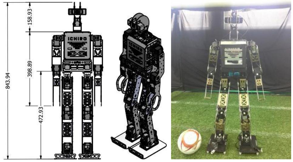
Design of robot humanoid have 20 degree of freedomwhich is 12 degrees of freedom on the feet, 6 degrees of freedom onthe hand, and 2 degrees of freedom on the head for pan and tilt. Mechanical design on shape and function of this robot are adjusted for the ability on intelligence to play football. The size of the robot's shape, hand length and footwear area follow the rules of the robocup organization. Design of robot is created using reference from the Nimbro - OP robot which is a robot team from Germany [2].
Design of the robot is not entirely the same with the Nimbro- OP, there are some modifications reduction on the head, body, hands and feet and have height of robot approximately in 84 cm. This is due to the limited material and cutting process. At that size, the robot can play at the teen-size and teen-size category in a robocup game. The material used in this robot uses aluminum alloy 5052 type with of 2mm and 3mm thickness and cutting use laser CNC machine. The process of cutting and bending aluminum is done with a low precision, so the part of robot is one of the problems in robot's balance. Drive of the robot in this design uses Dynamixel servo type MX-106T for feet, MX-64T for hand and MX-28T for head. Determination of the type of servo are suitable to the needs of robots in using great force in every movement. The mechanical design and realization of humanoid robots are shown in Figure 1.
2.2. Electronics of Robot
Robot cannot play football without the artificial intelligence that is planted in the robot. Robot equipped with Intel Core i5 NUC PC that has the ability to process up to 2.7 GHz and has a capacity of 4GB of RAM and using 120 Gb SSD for storage. Intelligence of robot and the determination of various actions will be performed on this controller, so this controller is called the main-controller. The second controller isCM-730 called the sub-controller. CM-730 will receive command data from the main controller to move the joint on each servo. The main- controller and sub-controller are connected using a serial communication line while the sub-controller is connected to the servo using the Half Duplex TTL communication line. Mini Maple is connected into the main-controller using serial communication lines. The mini maple will carry information on robot pressure center data that treads on the robot's footwear to be processed on the main-controller in the robot balance system.
3.1. Vision
Vision ability is the main thing in the game of robot soccer. Ball, goal, and line have same color, which is white [1]. Various methods have been tested and optimized in order to distinguish between the ball, the goal and the line.
At the ball recognition, the ball detection feature using the Histogram of Oriented Gradient (HOG) method. Characteristic of HOG features of a ball is showed by gradient distribution in the form of vector line. HOG feature results in doing the process of learning using Support Vector Machine (SVM) to generate a model that is used as a reference for detection. So that the process of ball recognition will be obtained [3].
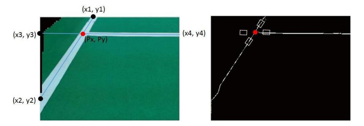
On the goal recognition, because of the color and the shape of the goal has a same construction with the line, so the goal recognition feature is added with the color of the field. In this case, the goal which is detected will always be perpendicular to the goal line. When the goal line and the goal intersect, it will become an interved T- shaped, and then it will be drawn upwards to the boundary line of the color of the field. If the obtained data lines reach the perimeter of the field color, then it will be used as reference of goal data. So in this case, the process of goal recognition begins with line recognition feature. The line recognition using hough transform method which obtained two crossovers, then the line is searched middle position value using the following equation :
$$(P_x, P_y) = \left(\frac{(x_1y_2 - y_1x_2)(x_3 - x_4) - (x_1 - x_2)(x_3y_4 - y_3x_4)}{(x_1 - x_2)(y_3 - y_4) - (y_1 - y_2)(x_3 - x_4)}, \frac{(x_1y_2 - y_1x_2)(y_3 - y_4) - (y_1 - y_2)(x_3y_4 - y_3x_4)}{(x_1 - x_2)(y_3 - y_4) - (y_1 - y_2)(x_3 - x_4)}\right)$$
When the midpoint of the intersection line is found, then every side in the midpoint of the intersection line will be checked. If it got 2 points, the line is known as the L- line features. If there are 3 points, then the line is known as the T-line features. Intersection of L-line is always at the end of the field, while the T-line is in the middle of the field. It can be used as a reference for recognition of localization position of each robot. When the position of the robot location known by using the line features, the goal position can be predicted [4].
3.2.1. Estimation and Determination Center of Pressure
Loadcell type YZC-133 has nonlinear specification of 0.05% full scale and voltage as the output of data. Therefore, it is necessary to convert the data to mass units. The voltage values obtained will be difficult to convert into mass because of its own non-linear loadcell. To overcome this, it must obtain the relationship between the actual mass of the object and the measured voltage by making data with various variations of the object. From that point, it will get characteristic and relation between mass with measured voltage to get mass equation. The result of the equation is changed into pressure. So each loadcell has its own pressure data. By looking at the each obtained of pressures and known size of foot, it can be calculated to get the center position of pressure on one of bases robot. Figure 4 shows the determination of the pressure center point on one foot.
The equation for obtaining the center of pressure on footwear is in equations 2 and 3 where Xo is the distance between the loadcell with the outer footwear in the x and y coordinates is the distance between the loadcell with the outer foot in the coordinates y. dx and dy are the distance between loadcell.
$$Xcop = X_0 + \frac{(F2+F4)*dx}{Ftotal}$$
$$Ycop = Y_0 + \frac{(F_1 + F_2) * dy}{Ftotal}$$
3.2.2. Calculation of Center of Pressure on Robot
When the center position of pressure on each footwear is obtained, the data will send to the controller that is on the robot body. The data will be processed to obtain the position of the center of pressure on the robot that tread on the condition at that time. From the data, it will get the center of pressure with using equation 4 and 5. fw is the width of the foot and df is the distance between the right foot and left foot.
$$Xcop = (fw + \frac{df}{2}) + (Xcopl - Xcopr)$$
$$Ycop = (Ycopl + Ycopr)/2$$
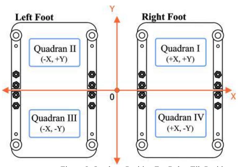
Coordinat of the position(0,0) for the center of the pressure is changed to the middle position and is determined as a robot balanced condition. From the positioning of the center, condition of robot when standing will be divided into 4 conditions seen from the quadrant of cartesian coordinate position. Figure 5 shows the location of each quadrant in robot footwear for the position of the center of pressure.
3.2.3. Calculation Angle of Condition From Center of Pressure
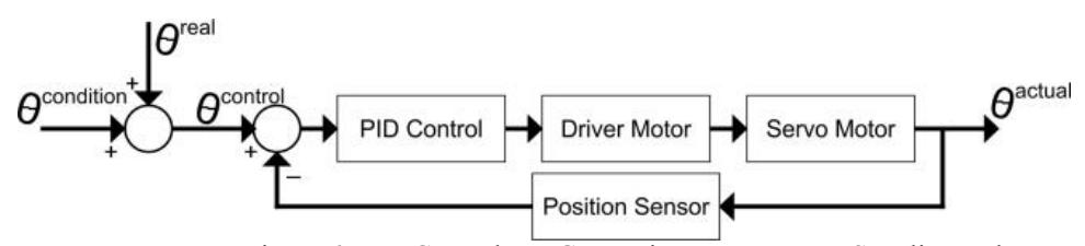
The position of the center of the robot pressure when robot is in balanced condition are located at the coordinate position in (0, 0). In these conditions, the robot is at the condition of the center of mass and center of gravity. So when the position of the center of the robot pressure is not in the center coordinate position (0, 0), the robot will be in an unbalanced condition and need to be calculated the condition of the robot for make return to a balanced position. Control for the calculation and positioning of the signal error using PID control.
3.2.4. Generate of Standing Posture Robot
Standing posture is fundamental to the movement of the robot. Various actions of the robot will begin and end with the standing posture of robot. If the robot's standing posture is not in the right condition, it will cause difficulties in doing other actions such as walking or kicking conditions and will easily fall. To obtaining a robot standing posture can be done with two stages, that is the generation of posture based on center of mass on robot and posture generation with PID control of the center of pressure position data.
Generating posture based on center of mass is done by forward kinematics method. The angle value on each servo is determined until standing position is established. In the determination of standing postures, robots are required to stand on the right center of mass at the center of gravity in order to obtain a balanced condition.
Generation of robot standing posture is by looking at the central data of pressure on the robot. When the robot standing posture has been made before, the robot is placed on the floor to see if the robot pressure is in a central condition. A balanced center position pressure condition is required to be in coordinates (0,0). If a robot pressure center position is not located at the center of the coordinates, then the error value is calculated to obtain a condition which is then added to the original obtained on the first posture generation to obtain a new posture. The control to obtain a new standing posture from the error center position of error value using the PID controls shown in Figure 6.
3.2.5. System Balance of Robot
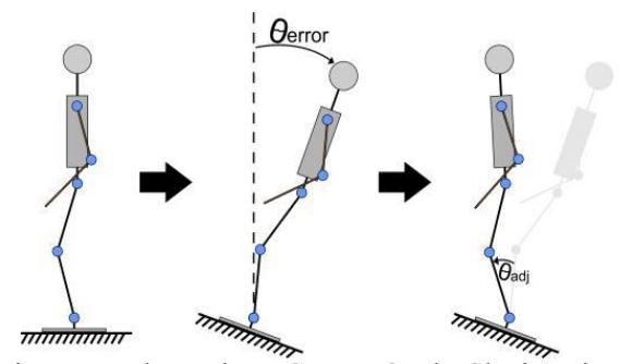
System Balance becomes the most important thing in the robot to keep the robot in maintaining the desired position. In a standing posture, each servo maintains a predetermined angle of position in standing. When the robot stands on uneven floor, the robot will fall if each servo retains the specified angle position in standing. So, by using the information of the position from center of pressure robot, robot can self-balancing from uneven floor.
Robot use the servo on the legs to be pulled forward for self-balancing. The purpose of this is to pull the position of the center of the robot pressure so that all the soles of the feet get the same pressure to obtained a balanced coordinate position. Illustration of robot balance system is shown in Figure 7.
4. Conclusion
The test results of Ichiro robot development in this year includes the design and development of the walking and the vision of robot. On the development of walking, the robot can run on artificial grass by changing trajectory planning on walking gait. The result of the walking test on synthetic grass is robot speed is 20 cm/sec. The vision design include ball, goal, and line recognition, which are have white color. Ball recognition is using HOG method which is successfully detected, whereas goal recognition is using detection methods based on the position of line and color field. So now, Ichiro team already has an ability to join RoboCup 2018.
References
[1] RoboCup Soccer Humanoid League Rules and Setup, https://www.robocuphumanoid.org/ [2] M. Schwarz, J. Pastrana, P. Allgeuer, M. Schreiber, S. Schueller, M. Missura, and S. Behnke. "Humanoid TeenSize Open Platform NimbRo- OP". pp. 568–575. Berlin, Heidelberg: Springer Berlin Heidelberg, 2014. [3] Hafez Farazi, Phillip Allgeuer, and Sven Behnke. A monocular vision system for playing soccer in low color information environtmens. In Proceedings of 10th workshop on Humanoid Soccer Robots, IEEE-RAS Int. Conference on Humanoid Robots, Seoul, Korea. (2015) [4] Budiono, I. Collaborative Humanoid Soccer League on Darwin-OP Platform Based on Rule of KRSBI 2015. ITS, Surabaya. (2015)