EDROM Humanoid Teen Size 2019
Alan N. de Paula, Arthur M. Nonaka, Gabriel R. X. de Araújo, Gustavo N. Souza, Hericles F. Ferraz, Iago A. Peixoto, Ísis G. Teixeira, Jhonas P. Moura, Jônatas A. Matos, Lorena F. Costa, Murilo M. Venâncio, Rogério S. Gonçalves, Ronaldo C. de Almeida
Universidade Federal de Uberlândia, Faculdade de Engenharia Mecânica, Av. João Naves de Ávila 2121, Bloco 1M Uberlândia, Brazil
www.edromufu.wixsite.com/edromufu
Abstract This paper describes the updates and new developments on the humanoid robots made by team EDROM since their participation in Robocup 2018. The team intends to participate in Robocup 2019 Humanoid Teen Size category. This paper describes current state of the robots' software and hardware, besides planned future work.
1 Introduction
The EDROM team - from Portuguese [1], team of development in mobile robotics – was created in 2010 and participates in the CBR - Brazilian Robotics Competition and LARC - Latin America Robotics Competition - since then. The team also has three participations in the RoboCup - in 2013, 2014 and 2018 – which had a great contribution in the improvement to our projects.
Unfortunately, due to electrical problems our team couldn't properly compete on the last RoboCup, in 2018. However, thanks to other teams' collaboration with knowledge sharing we could find and fix the problem more quickly. This paper encompasses the team work done since then.
2 Overview
The project is currently divided in 5 knowledge groups: mechanical structure, electrical system, computer vision, humanoid movement and robot's behavior. Nowadays, the team works in two robots with different behaviors: attacker and goalkeeper. Each robot has 20 degrees of freedom Robotis Dynamixel's actuators [2-3] that are connected to aluminum frames through screws.
The software is processed in an Intel® NUC [4] computer with Ubuntu 16.04 operating system and an Arduino [5,6] for input/output functions such as starting and stopping the behavior. The electrical circuit is responsible for ensuring the correct voltage and current for all servomotors and the computer, besides creating security mechanisms to avoid electrical damage. Other components are powered indirectly by the Intel® NUC's USBs.
The robot's software is composed by multiple processes that communicates using the ROS framework [6-7]. This architecture makes the project more modular and helps future growth, besides enabling the use of multiple programming languages with ease.
3 Mechanical Structure
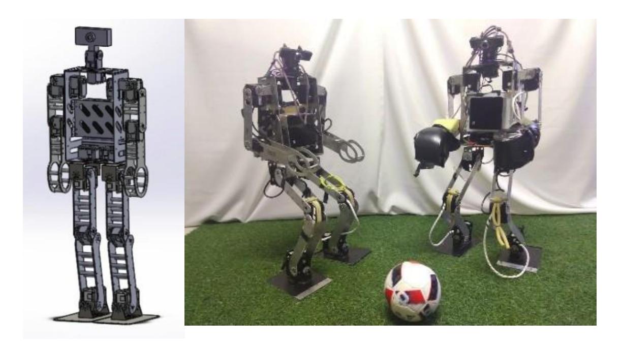
The mechanical structure was projected according to the rules of the humanoid soccer competition [8] and inspired by the open source NimbroOP project [9]. The team made use of the SolidWorks software [10] for the design and prior analysis of the structure's stiffness, Fig. 1(a).
This 3D project is also used for generating the robot's URDF file [11] which is used for the Gazebo's simulation [12] and to create the inverse dynamics model used to generate the walking motion.
4 Electrical system
The hardware is composed by the following components:
- Controller Intel® NUC 6i3SYK.
- Servo Motors Robotis Dynamixel MX-64 and MX-106.
- Cables.
- Battery LiPo 14.8V and 5000mAH.
- Camera Genius WideCam F100.
- DC-DC Step Up and Down module.
- Expansion Board OpenCM 485.
- Fuses.
- Diodes.
- Sensor Phidget Spatial model 1042 (compass data is not used).
- Switch buttons and LEDs.
- USB to TTL converter.
The battery is connected to a button following by three buck converters in parallel that powers the servo motors and the computer.
The battery offers 16.6V when fully charged and 14.8V when discharged. Since the motors operate in the range of 10-14.8V [13], the voltage needs to be lowered to power them properly. For it, we use two parallel DC-DC Step Down module, each one is connected in series with two diodes in parallel, these components are positioned that way to allow the current transmission, because the DC-DC Step Up and Down module allows up to 10A, while the diodes just 6A. The voltage converters are connected to the Open CM 485 Expansion Board [14] that powers all the servo motors connected in series.
The third, is a DC-DC Step Up module which is used to increase the voltage because the Intel® NUC computer needs 19.0V to operate. The controller is connected by the USB to a TTL converter which is connected to a fuse, as a safety component to avoid over current on the data channel.
The USB to TTL converter is a project called Mojtaba [15] in homage to the Iranian team AUTMan [16] who gave one of their converter to EDROM in 2014, after the team's converter broke. Since them, the team keeps developing a converter based on the one given by the Iranian team.
The electrical circuit also has switch buttons used to turn the power on/off, and with LEDs that informs the state of the switches. There is also an Arduino connected to the computer which is used to connect buttons that start and stop the robot's behavior.
5 Computer Vision
The vision is responsible to locate several objects of interest, such as the ball, goal posts, robots, and landmarks, then send this data to be processed by the Behavior. In order to process the images and retrieve this data, it's used the OpenCV [17] library to capture the live video feed, and TensorFlow [18], to process the feed and return the resulting objects and their location in the image. Since it's faster to integrate, and requires less data in comparison to training our own neural network, we use Transfer Learning in Deep Learning to train the neural network. The model that was taken as the source of the knowledge was Single Shot MultiBox Detector [19] with MobileNet [20] as the base network. To get the images necessary for training the network, it was used the ImageTagger [21] tool provided by the Hamburg Bit-Bots Team [22].
The possibility to change the model to return the mask/contour of an object instead of the Region of Interest is being studied, it would greatly improve the confidence in locating these objects, but it also gives a hit in performance that may make it impractical.
6 Humanoid Movement
The movement software is divided in four sub areas: motor communication, walking trajectories, alternative movements and the movement manager. The motor communication process takes the commands which comes from the other movement nodes and translates to the Dynamixel protocol of communication [23]; the package can be sent to the USB to TTL driver then.
The current approach for the walking trajectory generation is considering the ZeroMoment-Point theory [24] to create dynamic balance in humanoid walking. This is done by approximating the robot dynamics to a linear inverted pendulum, both for mathematical simplification and deriving the motion equations [25].
Alternative movements like kicking or getting up are created manually using an original software which saves the encoder readings and necessary time for each pose in the movement. The complete motion can be then replayed when requested. Fig. 2.
Software developed to create motions. Fig 2.
| Motor 0 | Pose 3 | Pose 4 | Pose 4 | Pose 5 | 5 | Pose 7 | Pose | Pose 8 | ||||
|---|---|---|---|---|---|---|---|---|---|---|---|---|
| 0 | -96,88 | -101,27 | ĵ. | -58,99 | į. | -10,55 | ĵ. | -12,31 | 3,08 | 1. | ||
| Motor 1 | 0 | 100,57 | 107,87 | 66,37 | - | 20,48 | * | 22,07 | -1,32 | 1 | ||
| Motor 2 | 0 | -11,08 | -10,46 | ÷ | -10,11 | Ĵ | -6,15 | ÷. | -6,24 | -6,07 | ÷) | |
| Motor 3 | 0 | 18,37 | 17,67 | - | 17,41 | Ĵ | 11,25 | * | 11,25 | 8,09 | 1 | |
| Motor 4 | 0 | 106,55 | 78,07 | à w |
33,49 | 4 | 9,49 | 4 | 10,73 | 4,04 | 1 | |
| Motor 5 | 0 | -103,30 | -85,45 | Ĵ | -39,12 | - | -18,81 | ĵ. | -19,96 | 2,20 | 1 | |
| Motor 6 | 0 | -0,09 | 0,09 | * | -0,26 | ÷ | -1,23 | * | -1,58 | -2,99 | : | |
| Motor 7 | 0 | 1,49 | 1,85 | · · | 1,85 | - v | 0,53 | Ŷ | 0,79 | -0,97 | Ŷ | |
| Motor 8 | 0 | -1,93 | -1,85 | -1,76 | - | -2,29 | * | -2,46 | -2,81 | ( ¢ | ||
| Motor 9 | 0 | 0,35 | 0,53 | ÷ | 0,70 | ÷ | 1,05 | ÷ | 1,14 | -0,35 | ÷) | |
| Motor 10 | 0 | 19,60 | -11,60 | ÷ | -35,78 | Ĵ | -88,70 | -64,26 | -37,54 | 1 | ||
| Motor 11 | 0 | -17,58 | 10,81 | * | 33,32 | ÷ | 85,45 | 62,59 | 41,58 | - | ||
| Motor 12 | 0 | -142,86 | -145,93 | ÷ | -147,78 | - | -146,02 | 0 | -90,20 | -69,63 | 1 | |
| Motor 13 | 0 | -142,77 | -147,08 | - | -147,69 | ÷ | -146,20 | ÷ | -89,76 | -68,31 | ÷) | |
| Motor 14 | 0 | 0,26 | -0,18 | ÷ | 0,09 | ÷ | 1,93 | ÷ | 2,37 | -3,87 | 1.0 | |
| Motor 15 | 0 | 1,32 | 1,05 | * | 0,97 | - | 2,55 | * | 2,81 | 0,62 | ÷) | |
| Motor 16 | 0 | -91,87 | -92,31 | - | -92,66 | Ĵ. | -76,48 | - | -52,48 | -51,08 | - | |
| Motor 17 | 0 | 88,26 | 89,23 | ‡ | 89,85 | Ĵ. | 78,07 | 1 | 49,85 | 40,35 | 1.0 | |
| Motor 18 | 0 | -0,18 | -0,18 | -0,18 | Ĵ. | -0,18 | * | -0,18 | -0,26 | |||
| Motor 19 | 0 | 0,18 | 0,18 | ÷ | 0,18 | 1. | -0,18 | 1.0 | -0,18 | -0,26 | 1 | |
| Time | 1,500 | 1,500 | - | 1,500 | - | 1,500 | - | 1,500 | 1,500 | 1 | ||
| Pause time | 0,000 | 0.000 | 0.000 | 0.000 | 0.000 | 0,000 |
The movement manager communicates with the behavior processes and is responsible for calling the right movement and sending feedback. It is the bridge between movement and behavior and is responsible for stopping and starting other movement nodes. Nowadays, no form of closed-loop control is used in the movement, however the team is doing research in the area with the goal of having a more trustworthy motion in the future.
7 Robot's Behavior
The sub area that is called "behavior" consists in the integration of the whole project so that the robot is able to play soccer. There are processes capable of executing basic soccer actions like search ball, walk in the ball direction, position the robot for kicking and many others. Each action is called according to a state machine which also uses data from the Game Controller [26] to compose the robot's behavior. The team has two different codes for the attacker and the goalkeeper, which actively defends falling to the side if the ball gets sufficiently close.
Nowadays, the state machine manager is completely developed by the team. However, to increase maintainability and make the project more modular we intend to implement the behavior with ROS Smach [27] until the time of RoboCup 2019.
8 Conclusions
This document is a succinct description of the current state of EDROM's project. However, the team intends to develop and improve much more till the time of RoboCup 2019. There is also a full commitment that we will have a person with sufficient knowledge of the rules available as referee during the competition.
9 Acknowledgements
This research has been partially supported by the FAPEMIG, CNPq, CAPES, UFU and FEMEC.
References
- EDROM .: EDROM Equipe de Desenvolvimento em Robótica Móvel, http://edromufu.wixsite.com/edromufu.
- Trossen Robotics .: Dynamixel MX-64 Robot Actuator, http://www.trossenrobotics.com/p/mx-64tdynamixel- robot-actuator.aspx.
- Trossen Robotics .: Dynamixel MX-106 Robot Actuator, http://www.trossenrobotics.com/p/mx-106t- dynamixel-robot-servo.aspx.
- Intel .: Intel® NUC kit NUC6i3SYK, https://www.intel.com/content/www/us/en/products/boards- kits/nuc/kits/nuc6i3syk.html.
- Arduino .: Arduino Nano (V2.3) User manual, https://www.arduino.cc/en/uploads/Main/ArduinoNanoManual23.pdf
- ROS .: ROS, http://www.ros.org.
- ROS .: Ros Kinetic, http://wiki.ros.org/kinetic.
- ROBOCUP .: Rules "Ro- boCup", 2018. ROBOCUP SOCCER HUMONOID LEAGUE. RoboCup Soccer Humanoid League Rules 2019 competition, http://www.robocuphumanoid.org/wpcontent/uploads/RCHL-2019-RulesDraft.pdf .
- NimbRo .: NinbRo-OP2X, http://www.nimbro.net/OP.
- SolidWorks .: https://www.solidworks.com. 11.ROS .: URDF, Unified Robot Description Format, http://wiki.ros.org/urdf.
- Gazebo .: Gazebo, http://gazebosim.org. 13.ROBOTIS .: MX-106T / MX-106R, http://support.robotis.com/en/product/actuator/dynamixel/mx\_series/mx-106.htm. 14.ROBOTIS .: OpemCM 485 EXP, http://support.robotis.com/en/product/controller/opencm\_485\_exp.htm.
- Mojtaba's git .: , https://github.com/leoxbox.
- AUTMan team .: Bio-Inspired System Design Lab, http://autman.aut.ac.ir.
- OpenCV .:OpenCV, https://opencv.org.
- TensorFlow .: An open source machine learning framework for everyone, https://www.tensorflow.org/?hl=hi.
- Wei Liu et al, "SSD: Single Shot MultiBox Detector", arXiv: 1512.02325v5 [cs.CV], Dec. 2016.
- Andrew G. Howard et al, "MobileNets: Efficient Convolutional Neural Networks for Mobile Vision Application", arXiv: 1704.04861v1 [cs.CV], Apr. 2017. 21.Bit-Bots .: ImageTagger. https://github.com/bit-bots/imagetagger. 22.ROBOTIS .: Hamburg Bit-Bots, https://robocup.informatik.uni-hamburg.de/en/welcome. 23.ROBOTIS .: Protocol 2.0, http://support.robotis.com/en/product/actuator/dynamixel\_pro/communication.htm.
- VUKOBRATOVIĆ, Miomir; BOROVAC, Branislav. Zero-Moment Point — Thirty Five Years of Its Life. International Journal of Humanoid Robotics, v. 01, n. 01, p. 157–173, 2004. https://www.cs.cmu.edu/~cga/legs/vukobratovic.pdf.
- VENÂNCIO, M. M. Estudo e Simulação de Geração de Trajetórias do Caminhar de um Robô Humanoide Utilizando o Método do Pêndulo Invertido Linear. 2016. 90 f. Trabalho de Conclusão de Curso, Universidade Federal de Uberlândia, Brasil.
- bhuman .: Game Controller, https://github.com/bhuman/GameController. 27.ROS .: ROS Smach, http://wiki.ros.org/smach.