MRL Team Description Paper for Humanoid TeenSize League of RoboCup 2019
Hamed Mahmudi, Alireza Fatehi, Amir Gholami, Milad Moradi, Erfan Fathi, Amirhossein Ghiasi Sani, Golnoosh Rahmani, Alireza Mohafezatkar, Alireza Karimi, Arash Rahmani, Meisam Teimouri
Mechatronics Research Lab, Dept. of Computer and Electrical Engineering, Qazvin Islamic Azad University, Qazvin, Iran
Abstract This team description paper presents the specifications of the MRL TeenSize humanoid robot system which contains different parts including system overview, robot vision and motion control. MRL humanoid team is developed under the RoboCup 2019 rules to participate in the TeenSize humanoid soccer league competition in Sydney, Australia and like the last years we will introduce a referee with sufficient knowledge of the rules available during the competitions. We use self-designed and self-constructed robots to participate in the competitions.
1 Introduction
RoboCup uses soccer as a research area to develop a team of humanoid robots that can win the human world champion soccer team in 2050. In the Humanoid league, human-like fully autonomous robots play soccer against each other and meanwhile handle stable walking, visual perception of the ball, players, and the field, modeling and kicking the ball, and also self-localization. The RoboCup soccer playing robots introduce challenges in design, control, stability, and behavior of autonomous humanoid robots.
The MRL project was started in 2003 in the Mechatronics Research Laboratory in Islamic Azad University, Qazvin branch looking onward to enhance the knowledge of robotics and the MRL humanoid soccer league is aimed to develop a humanoid platform for research and education. Our research center has the honor to hold the RoboCup IranOpen from 2003 to 2018. MRL has nine qualified teams and has had a successful history in RoboCup for many years. Our humanoid soccer playing team is one of the developing soccer-playing humanoid robots in the RoboCup Humanoid League and has participated in RoboCup and IranOpen Humanoid League since 2011.
A brief highlights of our participation in the RoboCup and IranOpen competitions are as follows:
- RoboCup 2018: take second place in main competitions, first place in DropIn and third place in technical challenge.
- IranOpen 2018: take first place in main competitions.
This year we are planning to participate in the TeenSize humanoid competition at RoboCup 2019 in Sydney, Australia. Our mission is to fulfill our study in motion control, vision, world modeling, and artificial intelligence.
MRL Humanoid TeenSize team consists of some researchers and students from software, hardware, electronics, and mechatronics.
2 Overview of the System
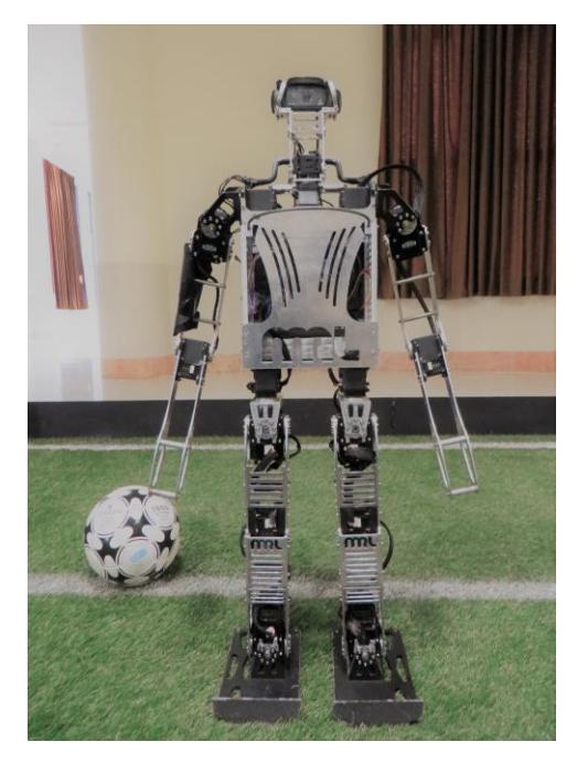
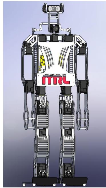
Amir is our new humanoid robot with 20 degree of freedom. Our robots have a well-known 20 degree of freedom structure with 83 cm tall and weight of 6.6 kg. All joints are equipped with Robotis Dynamixel MX series actuators. We have used six Dynamixel MX-106 for each leg, three Dynamixel MX-64 for each arm and two Dynamixel MX-28 in neck and head. The robot is powered by a 3-Cell, 5000mAH LiPo battery. The main processing unit is an Intel NUC 7th generation and power management is done by our self-constructed controller board which will be described briefly below. We also added eight Force sensors to the robot which will be explained.
Visual perception is done by a Logitech C920 normal webcam with 78° field of view. All mechanical parts of the robot are made of aluminum alloy 6061. We manufactured robot components by utilizing CNC Milling in order to increase accuracy.
Our software architecture is based on the UPennalizers RoboCup released code [1]. The Vision, world model and behavior modules are wholly rewritten and the walk engine is enhanced to address disturbances more efficiently.
2.1 Control manager
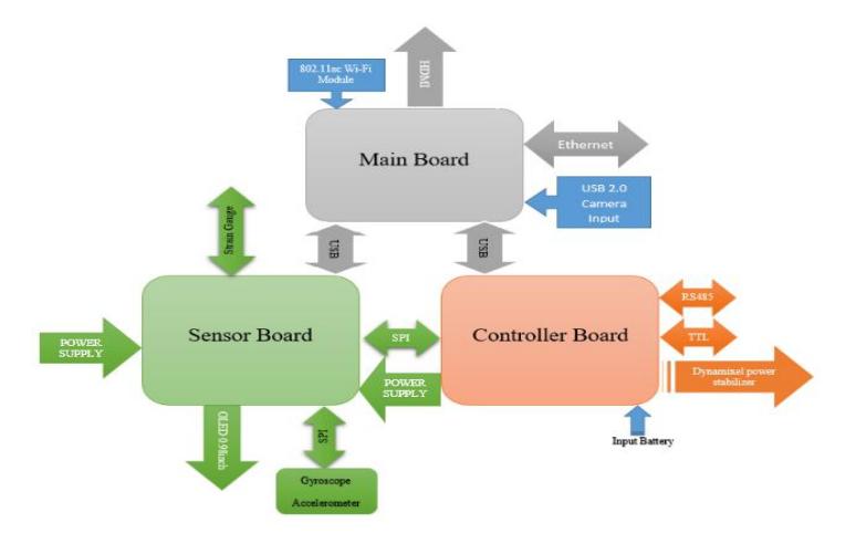
Last year, we designed our own control manager to gain more control over the whole system. This enabled us to deploy a new algorithm for fusing inertial sensors data and splitting actuators into three separate lanes to reduce the load when reading position of actuators. The new board increased the transaction speed between the main board, actuators, and sensors but as the strain gauges involved we decided to design a new board. The new control manager of the robot consists of two separate boards, which their functionality will be described briefly below.
Controller Board. The task of power management and actuators data streaming are done by this board. The processing unit of the controller board is based on an ARM STM32F405VE microcontroller. This board is designed to communicate with both T and R Dynamixel series at the same time. For the purpose of reducing the heavy load of data transfer, we have divided the communication into 5 independent lanes. Also, this board can supply the required power for the entire robot.
Sensor Board. The processing unit of the sensor board is based on an ARM STM32F405VE microcontroller. This board is equipped with 2 inertial sensors (gyroscope and accelerometer) and an OLED display and connected to strain gauges through a direct root. Another main responsibility of this board is estimating roll, pitch, and yaw, according to [2].
2.2 Strain Gauge
Maintaining stability is a critical issue in humanoid robots. In KidSize robots, the inertial sensors data is merely enough to resolve this issue. But in TeenSize robots, we need more feedback. Another type of sensors that can be used to maintain stability is the force sensitive sensors mounted on the sole of the foot. As the work of team Rhoban [3] on this matter, we also used four strain gauge connected to a driver board. This will enable our robots to measure the vertical forces applied to all four corners of the foot and calculate the COP (Center of Pressure) then report back every 12.5ms.
3 Goal Detection
Our method for goal posts detection is based on the segmented image and field boundary. We know that the goal posts are close to the field boundary. In the first step, we find all white pixels on the field boundary. Next, we extend the adjacent white pixels and form some regions that are the initial candidates. Among the initial candidates, there are candidates that are not acceptable. To filter out false candidates some sanity checks including ratio of white pixels, ratio of white pixels located on the field to the white pixels placed out of the field are applied. Relying only on this filters may result in detection of some false positives. To reject this false candidates we pass them among a strict filter. This filter is a cascaded adaboost classifier composed of 13 stages of weak decision trees. Here we have employed HAAR feature. To learn the classifier we have used some positive and negative samples prepared by an expert.
4 Motion Control
[Motion Control section content]
4.1 Simulation
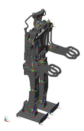
The primarily dynamical analysis before manufacturing the robot is needed to reduce errors which lead to damages to the robot. Accordingly, to avoid wasting additional expenses and time, the simulation of the robot is provided by Simulink software. Every designed component of the robot by CAD software (i.e. SolidWorks) is imported with all specification such as weights, moments of inertia and materials into the Simulink software. With considering the axis frames for each part, this feasibility is provided to assemble all components. The simulation is done with considering sensors like gyroscope, accelerometer and strain gauges which is used for all tasks of the robots namely walking generation, kick and etc.
4.2 Motor driver
Building taller robots requires more research on robot actuators. In our efforts to build taller robots we encountered a concerning problem about backlash in our current actuators. In addition to the motor's backlash, we faced some more issues listed below:
- Overheating in limited usage
- Breaking of gears under heavy loads
With this in mind, we decided to design a new servo motor that overcomes the problems mentioned before. In order to reduce backlash and prevent gears from breaking, we have reached a decision to change our motor drive system to harmonic drive, because it is well known for high-precision motion control and gears, approximately zero backlash and high torque which is superior to a conventional gearbox.
On our prototype driver we used an ARM STM32F103 as the main processing unit, combined with a MOSFET H-bridge. The feedback loop consists of a current sensor, an accurate voltage sensing circuit and an absolute resistive position sensor which enables the control algorithm to control motors position, speed and also torque. Some motions of the robot like walking and kicking are using inverse kinematics which gives angles, so the best solution for controlling the actuators is position control. It means that each actuator works according to the desired angle. For this purpose, a closed loop system is designed with angle feedback from the encoder of the motor. This feedback has an important role in accuracy of the controller. With the comparison between the desired angle and feedback angle, the driver motor acts as a position controller.
4.3 Yaw moment compensation
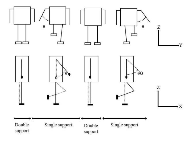
One of the most important problems in the humanoid robot is the dynamic balance around the z-axis. In order to have a stable walking, the momentum around the z-axis generated by the swing leg must be compensated. If the momentum exceeds the maximum static friction between the floor and the support foot, the foot start to slip and rotate around the z-axis [4, 5]. In human walking, the upper body compensates this momentum by swinging the arms and torso in the same phase of the swing leg. For this purpose, the arm strategy is used to compensate yaw momentum. By this compensation method, we have proposed to compensate the factors which generate yaw momentum. The arm trajectory should be adjusted with respect to the swing leg trajectory, which is required to formulate swinging leg acceleration and make a relationship between swing leg and arm.
As shown in Fig. 4, the walking pattern generation has several stages such as single support phase and double support phase, which are repeated continuously. Consequently, by measuring the acceleration of the swing leg during a time step, the speed motion of the arm is obtained.
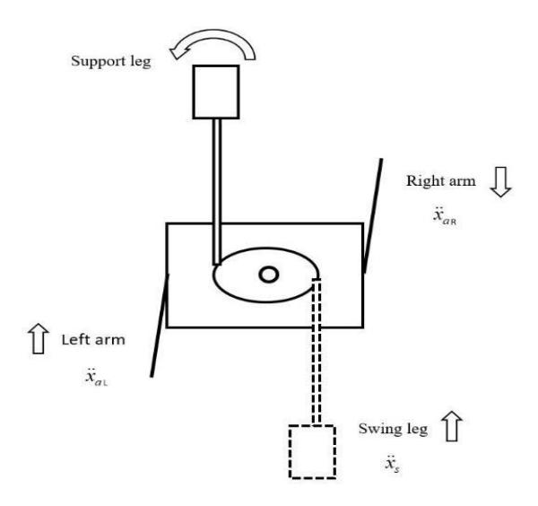
Fig. 5 illustrates the acceleration of swing leg and arms in which ̈ is swing leg acceleration, ̈ is the left arm acceleration with the same direction of the swing leg. On the other side ̈ is in the opposite direction of the right arm. Depending on the swing leg, the arm motion direction changes frequently.
4.4 Push recovery
Robots must be able to preserve their balance while standing and walking. Several controllers are designed to increase resistance against external forces such as push. The controllers are designed in MATLAB software to control hip, knee, ankle and arm joints. The operation of these controllers can be different depending on the force applied. For instance, when it is pushed from behind, robot stabilizes itself by pulling the arm back. As mentioned earlier the robot includes typical sensors like inertial measurement unit (IMU) that is attached to the torso, to detect changes in the desired center of mass orientation. According to the feedback of IMU sensor at any moment, if torso angles are greater than the desired angles, the controller starts to recover robot against falling down. With considering the different moving speeds, uneven surfaces and pushes, the controllers adjust different outputs for each joint. In contrast of our previous controller [6] the new controller is resisted against forces coming from the sides of the robot. Moreover the robot is able to handle stronger pushes.
4.5 Kicking
Due to the disturbances such as motor backlash, uneven playing field, collision with other robots, etc., before the robot kicking the ball with its left leg, it will open its left hand to the left side and will close its right hand; and the same method in right kicking. In the other hand because of the uneven surface or probability of collision with other robots, some forces might be applied on the robot and make it unstable. So robot should cope with these disturbances. For this purpose, a PID controller is used on the knee joint. A feedback from gyroscope is used to design the controller. Consequently when the robot contacts with objects a control signal will be send to compensate these disturbances.
5 Conclusion
In this paper we have presented the specifications of the hardware and software of MRL TeenSize humanoid robot system developed under the RoboCup 2019 rules. MRL commits to participate in RoboCup 2019 in Sydney, Australia with further enhanced hardware and software based on the achievements of previous year and also commits to introduce a referee familiar with the rules of the Humanoid League.
We use our self-designed and self-constructed robots and we are working on this platform with some interested researchers and students modifying and optimizing the platform in vision, motion control, world modeling, behavior, and embedded control board.
References
- Upenn RoboCup, Code, available online. Available from: https://fling.seas.upenn.edu/~robocup/wiki/index.php?n=Main.Code
- Allgeuer, P. and S. Behnke. Robust sensor fusion for robot attitude estimation. in Humanoid Robots (Humanoids), 2014 14th IEEE-RAS International Conference on. 2014. IEEE.
- Allali, J., et al., Rhoban Football Club–Team Description Paper.
- Ueda, J., et al., Momentum compensation for the fast dynamic walk of humanoids based on the pelvic rotation of contact sport athletes, in Humanoid Robots, Humanlike Machines. 2007, InTech.
- Hirabayashi, T., et al. Yaw moment compensation of biped fast walking using 3D inverted pendulum. in Advanced Motion Control, 2008. AMC'08. 10th IEEE International Workshop on. 2008. IEEE.
- Teimouri, M., et al., MRL Team Description Paper for Humanoid TeenSize League of RoboCup 2018.