AllemaniACs 2009 Team Description
Daniel Beck, Tim Niemueller
Knowledge Based Systems Group RWTH Aachen University Aachen, Germany
Abstract The increasing performance displayed by the participating teams in the different leagues and competitions of RoboCup lead to constant changes of the rules to reflect those improvements the teams made on the one hand and on the other they intend to drive future development in the particular leagues. In the Middle Size League the most prominent changes in the recent years have been the enlargement of the field, which now has twice the size as before, and the removal of the color markings from the field. Those changes in the rules and the progress made by other teams make it unavoidable to improve and refine one's own approach.
In our case, it became obvious that our old robots equipped with a differential drive weren't up to the challenge any more and needed to be replaced by a new platform. In this paper we give an overview of our current setup, sketch the design of our software system, and give a concise summary of innovative solutions the team realized recently. In particular, these are a Lua-based behavior engine, a kick device which is capable of playing low passes as well as high-kicks, a reactive, landmark-based approach to the navigation problem, and the extension of a known localization technique in order to account for the symmetry problem arising from the removal of the color markings.
Introduction
The increasing performance displayed by the participating teams in the different leagues and competitions of RoboCup lead to constant changes of the rules to reflect those improvements the teams made on the one hand and on the other they intend to drive future development in the particular leagues. In the Middle Size League the most prominent changes in the recent years have been the enlargement of the field, which now has twice the size as before, and the removal of the color markings from the field. Those changes in the rules and the progress made by other teams make it unavoidable to improve and refine one's own approach.
In our case, it became obvious that our old robots equipped with a differential drive weren't up to the challenge any more and needed to be replaced by a new platform. In this paper we give an overview of our current setup, sketch the design of our software system, and give a concise summary of innovative solutions the team realized recently. In particular, these are a Lua-based behavior engine, a kick device which is capable of playing low passes as well as high-kicks, a reactive, landmark-based approach to the navigation problem, and the extension of a known localization technique in order to account for the symmetry problem arising from the removal of the color markings.
Hardware Platform
Following the de-facto standard in this league the AllemaniACs hardware platform is omni-directional: the drive system is comprised of three drive chains, each consisting of a 90W motor, a reduction gear, and an Omni wheel. This configuration allows to steer the robot into any direction without any holonomic constraints. The drive system is completed by a hardware motor-controller which is connected to the computer over the serial port.
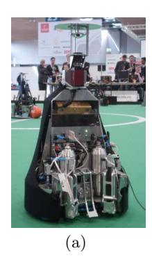
Besides the drive system, the second key-component of an omni-directional platform is the omni-directional camera which is mounted on the top of the robot (cf. Fig 1). Here we use a camera which can deliver images with a size of 1000 by 1000 pixels with up to 30 fps. The quadratic size of the image sensor is especially handy for this application since the maximal distance in which the robot can observe its environment is the same in the forward- as well as in the sidewards-direction.
Below the omni-directional camera system we have a Bumblebee-2 stereovision camera. The reasons for adding a second camera and a stereo-vision camera in particular are to obtain more precise positional information about objects in front of the robot (e.g., the ball). The stereo-vision allows to detect and even recognize objects of higher structural complexity more accurately (e.g., other robots, humans, or the goals which are not color-coded any more). For more detailed information about the object detection see Sect. 4.2.
The on-board computers we have on our robots are powerful Mini-ITX computer which are comparable to nowadays desktop machines in terms of equipment and performance. More precisely, the machines are equipped with a Core2 Duo processor running at 2 GHz, 2 GB or main memory, and a solid state hard drive. We opted for flash disks in favour of ordinary hard drives due to their increased robustness. The batteries which power the complete system are located below the computer. Here, we have so-called smart battery packs which report information about their status over a serial connection. Among the status information are the remaining voltage, the current, and the temperature. On a single charge the robot runs with those batteries for up to four hours.
Software Architecture
Building on our previous experience we redesigned and reimplemented our software framework for the control software. A robot software framework for a MIDDLE SIZE LEAGUE robot must thus be able to work at very high speeds and small latencies.
The FAWKES robot software framework is written in C++ and runs as a monolithic process with a main loop which is subdivided into certain stages (roughly, it implements the sense-think-act loop). The actual functionality (e.g., navigation, ball detection, localization, behavior etc.) is implemented in so-called plugins which can be dynamically loaded at runtime. A plugin consists of a number of threads. Each of these threads can attach to one of the processing stages in the main loop. All threads of the same stage are then run concurrently at the same time, allowing for exploiting the capabilities of multi-core CPUs. Slower or long running threads can choose to run concurrently to the main loop to not slow down the whole cycle.
From a developers perspective logical components are defined with certain inputs and outputs. A plugin then implements one or more of these logical components. This allows for an efficient design process of the software.
To distribute information across the robot software framework and to connect the components we follow a blackboard approach. The blackboard is a shared memory segment which is accessed via well-defined interfaces. These interfaces are defined in an XML file from which code is generated to enable access to the memory contents.
Whereas the framework and the low-level plugins are coded in C++ we make use of the Lua scripting language for programming robots' basic behaviors (e.g., intercept), the high-level agent is programmed in the logic-based programming language ReadyLog. We specifically opted for those languages because we are convinced that they are exceedingly qualified for their particular applications in the context of robot programming.
ReadyLog [1] is a dialect of Golog [2] which is based on the situation calculus. Besides the usual programming constructs like conditionals and loops ReadyLog provides nondetermistic constructs that allow the programmer to leave certain choices open. For instance, the programmer may decide to leave the choice whether to continue with program p1 or with program p2 open which is encoded in the program fragment nondet(p1, p2). Those choices constitute planning problems which are, given a reward function, solved by the decisiontheoretic planner build-in into the language. Since the language Golog has a formal semantics it is well-suited as a specification language for soccer theory in order to derive the robots' behaviors. An example for a specification of a soccer move can be seen in Fig. 2; for more details we refer the reader to [3].
By means of adaptor plugins FAWKES can exchange data over the Player [4] network protocol which allows us to connect the control software to the robot simulator Gazebo [4] (or Stage [4] if a physically correct simulation is not required) for development and testing purposes. More details on that topic can be found in [5].
Innovations
[Introduction to innovations section - organized by subsection below]
Lua-based Behavior Engine
For the agent program we follow a knowledge-based approach with decision theoretic planning. To make this feasible primitive actions are required, small execution entities for the robot that can be used during planning.
For this we have added a reactive layer to our software, the behavior engine, which provides a programming environment for these primitive actions, called skills. Examples for such skills are "goto position (x,y)" or "intercept the ball". The behavior engine employs the Lua [6] scripting language. It is light-weight, fast, and easy to embed. All libraries and executables required to run Lua code are less than 200 KB in size and independent benchmarks have shown it as one of the fastest scripting languages [7, 8]. It has a C API that allows for calling Lua from C and vice versa.
With this API the Lua environment has been embedded into FAWKES as a plugin. With an automated wrapper generator code is produced to allow access to the blackboard from the Lua environment. With this everything that is provided by a component can be accessed.
Behavior is modelled as hybrid state machines [9], extended to be more efficient for skills. With this the behavior can be formally specified and graph visualizations can be generated while the application is running for easy debugging of the behavior.
A scripting language in general is beneficial for programming the behavior as it frees the behavior designer from many problems like memory management prevalent in programming environments like C++. Although developing skills by formal specifications is preferred, using a full-featured scripting language gives more flexibility and allows for deviating from the formal process to rapidly prototype behaviors to quickly verify and reject ideas for new behaviors.
With our activities in the ROBOCUP@HOME LEAGUE and the new STANDARD PLATFORM LEAGUE in mind the behavior engine is designed to be domain-, platform-, and league-independent. Certain skills developed for the humanoid Nao robots can be used unchanged on the mid-size robots and vice versa.
Stereo Vision
In the course of making the field environment less artificial there have been several profound changes in the recent years: the field was doubled in size, all color markers have been removed, and one could see rapidly changing lighting conditions at the last events. Especially the latter two impose major challenges on color-based image segmentation techniques. These are often employed during preprocessing and image in order to detect certain types of objects in the image based on their color (e.g, the ball, other robots, the field boundaries, etc.).
Under these circumstances we opted to increase the dimension of perception and integrate a stereo-vision camera into our robots. Here, the plan is to validate and refine the information which is obtain by means of color detection and segmentation techniques on basis of the 3-dimensional reconstruction of the scene as it is provided by the stereo-camera. Certainly, this is only possible for objects which are in front of the robot and, thus, in the viewing angle of the stereocamera.
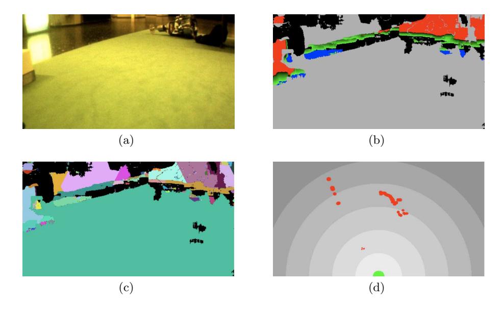
A first step in this direction has been made. We adapted a segmentation scheme which was developed for the segmentation of color images [10] for the segmentation of the depth maps as they are provided by the stereo-camera. The process of extracting obstacle position from the depth-map is split up in three steps. At first, the depth map is transformed according to the position and the view angle of the camera. This results in a height map—each pixel of that map contains the height above floor level of the object seen at that position (cf. Fig. 3(b)). Then, the hierarchical segmentation algorithm as it is described in [10] is run on the height map. On each level of the hierarchy the image is subdivided into overlapping islands which in turn consist of islands of the underlying level in the hierarchy. On the lowest level the islands are made up of the pixels of the images. For neighbouring islands it is checked on each level whether the given criterion for joining them is fulfilled. Here, the criterion for a join is the average height of the area covered by the island in question. The result of the segmentation is a number of islands each covering an area in the image with roughly the same height above floor level, i.e., each area with an average height not equal to zero corresponds to a particular obstacle (cf. Fig. 3(c)). Of course, the stereo-reconstruction of the scene is not perfect and, consequently, there might be false values as well as so-called unknown regions, regions for which no depth values could be determined. This is taken care of during the segmentation process—unknown regions smaller than a certain threshold and unlikely height values (e.g., negative ones) are simply ignored, for larger unknown regions, up to a certain extent, the height is interpolated from the surrounding regions. Lastly, the relative positions for all detected obstacles are determined (cf. Fig 3(d)).
Reactive Landmark-based Navigation
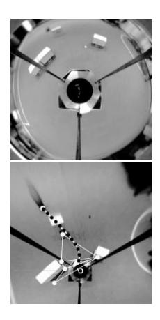
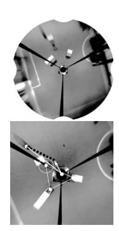
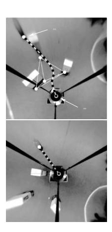
For the navigation we employ an algorithm which was presented in [11]. It combines the search for an short and safe path with reactive collision avoidance mechanisms. More precisely, over the set of detected obstacles a Delaunay triangulation is computed. In a Delaunay triangulation two vertices are connected by an edge if there exists a circle over those two vertices in question and no other vertices are located within that circle. Intuitively that means that the obstacles representing the corner points of the triangle the robot is located in are the obstacles closest to the robot. Obviously, the safest point to pass between two obstacles is to pass them right in the middles, Consequently, a traversal graph is constructed by connecting the midpoints of the edges in the Delaunay triangulation of neighbouring triangles. Over that traversal graph we conduct an A∗ search for a path. The evaluation function combines the length of the path with the clearance between the obstacles that are passed along that path. Thus, it can be balanced between length and safety of the path. The high dynamics of the soccer domain is attributed to by recomputing such a path in every cycle. Additionally, to avoid an imminent collision, a collision-avoidance path to the next waypoint on the original path is computed using a force field approach.
The dynamic, obstacle-dependent subdivision of the free space leads to a considerable reduction of the necessary search depth in comparison to grid-based approaches which divide the space into grid cells with a fixed size. Together with the low complexity for constructing the traversal graph this makes it tractable to recompute the path in every cycle and, thus, react to the rapidly changing environment. An illustration of the algorithm can be seen in Fig. 4.
Collaborative Localization
Our approach for localizing the robots on the field is based on the standard Monte Carlo localization algorithm. In the images obtained from the omni-directional camera the white lines on the field are detected by checking for transitions from green to white and back to green along rays from the center to the outer edges. The midpoints of the intersection of the ray and the lines are used as samples for the Monte Carlo localization algorithm; the likeliness of a sample is determined with respect to the current estimation of the robots' pose and a model of the field lines.
Since the color markings on the field have been removed the field is completely symmetric and a single robot, without any prior knowledge, cannot decide on which half it is located. Since the robots already exchange information about detected obstacles and their respective estimation of the ball position we integrate this into the Monte Carlo update. This allows to favor the one of the two symmetrical positions for which the robot's own sightings of the ball or other obstacles conforms with its team-mates' sightings. Although this ensures that the localization is consistent within the team it does not yield a solution for the global localization problem. Therefore, we make the plausible assumption that at least one robot (e.g., the goalie) can correctly solve the symmetry problem and thus knows its correct global position. Given that knowledge the global localization problem can be solved for the complete team.
Three-legged Pneumatic Kicker and Ball-guidance
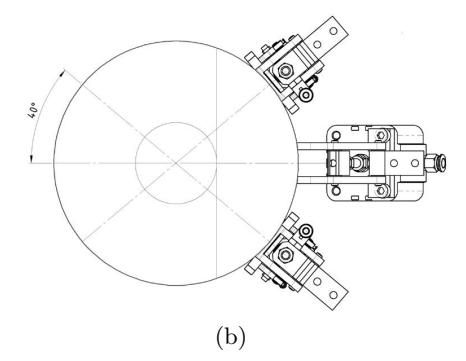
We designed our kick device not with the idea in mind to be as powerful as possible but what we longed for was maximal control over the ball in order to make well directed passing among the robots possible. Therefore, we mounted three kick devices on the robots (cf. Fig 1(b)): a stronger kick device in the middle and to each of its sides another kick device which is mounted at an angle of roughly 40°. All three kick devices are pneumatic—the central kick device is powered by a pneumatic cylinder whereas the sides are powered by pneumatic muscles which allow for a very space-saving design. The central kick device is intended to do a high-kick; it is strong enough to kick the ball over an opponent player. The kick devices powered by pneumatic muscles are intend for passing, they can be triggered conjunctively to play the ball in the front direction or selectively to play the ball slightly to the left and the right, respectively.
Furthermore, we have a pneumatic-controlled ball-guidance mechanism which consist of two small arm which can be extended either on the right side of the kick devices or on the left side. The intention behind this is to keep the ball in front of the kick devices while driving a curved path, e.g., during a right-turn the left arm is extended and during a left-turn the left arm is extended.
References
- Ferrein, A., Lakemeyer, G.: Logic-based robot control in highly dynamic domains. Robotics and Autonomous Systems, Special Issue on Semantic Knowledge in Robotics 56(11) (2008) 980–991
- Levesque, H.J., Reiter, R., Lesperance, Y., Lin, F., Scherl, R.B.: Golog: A logic programming language for dynamic domains. The Journal of Logic Programming 31(1-3) (April-June 1997) 59–83 Reasoning about Action and Change.
- Dylla, F., Ferrein, A., Lakemeyer, G., Murray, J., Obst, O., Röfer, T., Stolzenburg, F., Visser, U., Wagner, T.: Towards a league-independent qualitative soccer theory for robocup. In Nardi, D., Riedmiller, M., Sammut, C., Santos-Victor, J., eds.: RoboCup 2004: Robot World Cup VIII. Volume 3276 of Lecture Notes in Computer Science., Springer (2005) 611–618
- Gerkey, B., Koenig, N., Vaughan, R., many others: The Player Project. http://playerstage.sourceforge.net retrieve Jan 30th 2009.
- Beck, D., Ferrein, A., Lakemeyer, G.: A simulation environment for middle-size robots with multi-level abstraction. In Visser, U., Ribeiro, F., Ohashi, T., Dellaert, F., eds.: RoboCup 2007: Robot Soccer World Cup XI. Volume 5001 of Lecture Notes in Computer Science., Springer (2008) 136–147 ISBN: 978-3-540-68846-4.
- Ierusalimschy, R., de Figueiredo, L.H., Filho, W.C.: Lua An Extensible Extension Language. Software: Practice and Experience 26(6) (Jan 1999) 635 – 652
- Ierusalimschy, R., de Figueiredo, L.H., Filho, W.C.: The Evolution of Lua. In: Proceedings of History of Programming Languages III, ACM (2007) 2–1 – 2–26
- The Debian Project: The Computer Language Benchmarks Game. http://shootout.alioth.debian.org/ retrieved Jan 30th 2009.
- Henzinger, T.A.: The theory of hybrid automata. In: Proceedings Logic in Computer Science 1996, IEEE (Jul 1996) 278–292
- Rehramm, V., Priese, L.: Fast and robust segmentation of natural color scenes. In: Proceedings of the Third Asian Conference on Computer. Volume 1351 of Lecture Notes in Computer Science., Springer (1998) 598–606
- Beck, D., Ferrein, A., Lakemeyer, G.: Landmark-based representations for navigating holonomic soccer robots. In: RoboCup 2008: Robot Soccer World Cup XII. Lecture Notes in Computer Science, Springer (2008) To appear.