The Hong Kong Dragons Robotic Soccer Team Description Paper 2009
Mark Wenig, Peter On, Kenneth Pang, William Lai, Ka Lok Chan
City University of Hong Kong Department of Physics and Materials Science 83 Tat Chee Avenue Kowloon, Hong Kong
Abstract This paper describes the City University of Hong Kong middlesize robotic soccer team called the Hong Kong Dragons. We describe the robots' hardware and the image processing techniques used to calculate the positions of the robot, the ball and the opponents, as well as path planning and behavior control.
Introduction
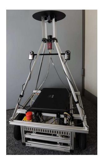
The Hong Kong Dragons RoboCup Team consist of 3 robots as shown in Fig. 1. Since this is our first time to participate in a RoboCup competition and we only had about 2 months of preparing time, we focused on the image processing techniques since this project is designed to provide our students with some hands-on learning activity where they can apply their knowledge acquired in the accompanying course about digital image processing. For the hardware we rely on the VolksBot concept [1] which is a modular mobile robot construction kit. In the following we will describe this hardware architecture and the software system design.
Hardware architecture
The first generation of the Hong Kong Dragon robots are controlled by a standard notebook which controls the drive unit via the VolksBot Motorcontroler and the kicking device via USB. Sensor data is coming from an omnivision camera and two web cams.
Drive unit
The robot is equipped with a differential drive with two driven wheels (150W DC drives) and two passive wheels.
Kicking device
We use a pneumatic kicking mechanism with 24V DC magnetic valve and a 0.5l pneumatic pressure vessel at 10 bar. This kicking device is not ready yet and is not shown in Fig. 1. The kicker will be mounted at the front side of all robots and can be controlled via an USB interface.
Vision system
The catadioptric vision system which is mounted on our robots was built by the Fraunhofer Institut Intelligente Analyse- und Informationssysteme (IAIS) and features a hyperbolic mirror which produces an opening angle of about 180◦ and an AVT Marlin F-146C IEEE 1394 camera with a resolution of 1392 x 1024 pixels. Additionally, we use two Locitech QuickCam Pro for Notebooks with a USB connection and 1600 x 1200 pixels. Those two cameras are facing forwards to allow for stereo tracking.
Software system design
The software is running on Windows Vista and was developed using Visual C++. We use a single-threaded process with a control loop, starting with the capturing of the images from the three cameras, storing the images together with time stamps, running the different modules for selflocalization, ball localization, opponent localization, behavior analysis and path planning and finally sending the determined signals to the drive module.
Selflocalization
The calculation of the robots position on the field is based on the line and circle markings on the floor and uses the omnivision camera only. The first step is to use the structure tensor technique [2] to get reliable edge information. This information is used to reduce the model space of the following Hough transform [3]. For this module we use the average of the red and blue channel only in order to maximize the difference between the while lines and the green floor. Instead of removing the lens distortion, we include the lens distortion model in the conversion from data to model space. The camera parameters are determined using the DLR CalDe (camera Calibration Detection tool) and DLR CalLab (camera Calibration Lab) [4]. The difference between the derived line and ellipse parameters and the parameters of the lines and circle projected into the undistorted image plane is minimized to derive the robot's coordinates and orientation.
Ball localization
For the localization of the ball, we use the stereo vision system consisting of two web cams. Again a Hough transform is used to determine circle parameters. For this module we use only the red channel. The radius of the circle can already provide some depth information, but since we have two cameras, we combine this estimate with the distance determined by triangulation.
Opponent localization
Opponents are classified using a color segmentation of the web cam images. Every region in the image that has the color of the opponents color marker flows into neighboring pixels classified as black using a flood fill algorithm. The lowest pixel of a connected region is projected onto the ground to determine the location of the corresponding opponent.
Behaviors and tactics
We distinguish only 3 different basic behaviors: attacker, defender and goalkeeper. The field players can change their behavior using the first two states, the goalkeeper using the last two. The goalkeeper is designed like the field players, which means he has the kicker and web cams at the same side of the robot and therefore can not move sideways. In goalkeeper mode the goalkeeper simply stays on the goal line and rotates to face the ball. If an opponent approaches with the ball and no defender is between him and the ball, he switches to defender mode. In this mode, the robot will approach the ball if no teammate is already doing so, tries to get hold of the ball and then tries to pass the ball to a teammate. If the goalkeeper can not find a teammate he will just pass the ball away from the goal, returns to the goal and goes back into goalkeeper mode. If a field player in defender mode can not find a teammate to pass the ball to, he will switch to attacker mode and moves with the ball toward the opponent's goal and tries to score. A defender without the ball tries to move to a spot in front of his goal. An attacker without the ball tries to get to the ball unless the defender has the ball in which case he tries to move to a position where he can receive the pass.
Since we only have three robots, we have one for each behavior state. Whenever one field player switches from one state to the other, the other player switches as well. At kick-of we start with the kicking robot being a defender, so that he immediately passes the ball.
Conclusion and discussion
The Hong Kong Dragons RoboCup team is a teaching related project focusing on digital image processing. So far it worked really well to motivate the students to learn about digital image processing and to improve their team working skills. In the future we plan to include students from other departments to get some experts working on other areas as well, e.g. hardware or strategy optimization.
References
- The VolksBot, http://www.volksbot.de/index-en.php
- Jähne, B.: Digital Image Processing, Springer, 5th edition (2002)
- Duda, R. O., P. E. Hart: Use of the Hough Transformation to Detect Lines and Curves in Pictures, Comm. ACM, Vol. 15, pp. 1115 (1972)
- Strobl, K. H., W. Sepp, S. Fuchs, C. Paredes, K. Arbter: DLR CalDe (camera Calibration Detection tool) and DLR CalLab (camera Calibration Lab), Institute of Robotics and Mechatronics, German Aerospace Center (DLR), Oberpfaffenhofen, Germany, http://www.robotic.dlr.de/callab