Mobility and agility with an improved sight
Fernando Ribeiro, Gil Lopes, Tomé Silva, António Freitas, Miguel Oliveira, Luis Novais
Grupo de Automação e Robótica, Departamento de Electrónica Industrial, Universidade do Minho, Campus de Azurém, 4800-058 Guimarães, Portugal
Abstract This paper briefly describes the main changes on Minho Team robots since the last RoboCup participation. Work has been carried out on the robots in order to constantly improve their capabilities, based on the experience from previous participations. The team stopped for one year in order to implement structural changes and to add new features. The main topics to deal in this paper are related to structural changes of the robot, the in-house development of a robust and configurable motor driver used for each of the three motors and the improvement in the robot head and vision system for a better sight. Also on this paper a description of the whole software changes and implementation, and the use of Object Oriented paradigm for robot programming.
1. Introduction
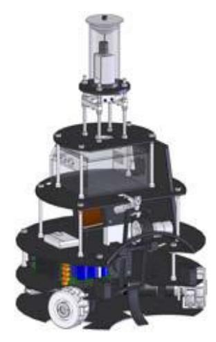
Minho Team has been participating on RoboCup for a long time, improving their robots year after year and this year is no exception. The previous generation of these robots was started in 2003 [1], and now a new generation is born. The robots were completely built in the University of Minho Robotics Laboratory (mechanics, electronics and software) and were first drawn in CAD software in order to test if all components would fit physically. Each robot consists of a physical bottom layer where 3 omnidireccional wheels are used to drive and steer the robot, along with the batteries and the kick capacitors. Next, there is a second layer where all the electronics that control the robot are placed, along with the horizontal kicker. On the third layer, the computer and wireless network boards are located, plus the vertical kicker and an optional ball dribbler. On the top of the robot is the vision head. Fig. 1 shows the robot drawn in the CAD software.
The robots have recently been tested on Minho Laboratory, and the tests have proven that the hardware is feasible and stable.
This paper starts with the description of the structural changes implemented on the robots, followed by the newly developed servo-motor driver and the technologies used to improve the robot's vision. The last part is dedicated to the software development in object oriented programming.
2. Structural changes
2.1 Introduction
The goal of the structural change was to substantially reduce the weight of the robot in order to take advantage of the 150W power of each motor. The original robot weights around about 40 kg and moves at a maximum speed of 0.8 m/s, whereas the new weight is one third of the original weight and the speed is approximately three times faster. One of the increasing premises of the Robocup competition is how fast a robot moves to the ball and dribbles it around. In that sense, robot's velocity is a top priority of any team.
To achieve that, the team had to rely on lighter and affordable materials to build the robot on. Carbon fibre was the first thought but due to the high market prices of this material, another quasi similar and cheaper solution had to be found. Each layer of the robot is made of a circular thin plate or board where the components are attached to. On the previous robots, these boards were made of aluminium with 3 to 5 mm thickness, also necessary to hold the heavy shocks when two robots dispute a ball. That can be seen by the worn collision areas and scratches of each robot. Since nowadays the robot control of each team is noticeably improved, the amount of collisions is also decreasing and thus, the excess of mass for robot robustness can be alleviated.
In that sense, a good compromise was found using materials such as fibreglass, foam and epoxy resins. The combination of these materials can produce very high hardness values (between 100 and 160 MPa depending on the epoxy resins [2]), enough to sustain heavy shocks in a much lighter board than the aluminium boards (typical hardness values of 167 MPa), although the latter is more ductile. This ductility can be considered an advantage of the aluminium because it does not tear or break in a shock but tends to bend, while the fibreglass board might break at the same impact force. Either way, a bent or a broken board are not a good prognostic for the robot's health nor for one's control.
Although one might think these are expensive materials this is not the case. Fibre glass and the foam are at perfectly acceptable prices and they just require some hand work.
2.2 New physical structure
To produce the boards, layers of fibreglass are used with polyethylene foam in between just to fill in the space, and epoxy resin. Two outer layers on each side of the board of fibreglass chopped strand mat are laid with the foam laid in the middle. This sandwich is then inserted into a vacuum controlled environment where the epoxy resin is poured over and spread to accommodate the whole board. When properly dried after several hours at room temperature, the final result is a solid hard board ready to drill.
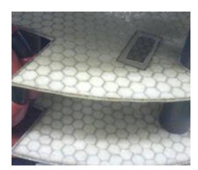
The fibreglass mat and foam are cut to the right board shape exported from the CAD hence taking the final shape before the epoxy resin. Some small holes on the board for the fixings are marked but filled with resin due to construction restrictions. These holes are drilled in the end when the resin is dried. Fig. 2 shows an image of the two base boards 0 and 1. To create a solid robot skeleton, it is necessary to consolidate the foundations between the boards. A PVC tubular structure is used to perform that connection creating a rigid pillar system.
When this whole process is finished a complete report will be written and will be made available to the RoboCup community so that other existing teams or new teams can use this technique and avoid wasting time testing materials.
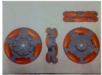
Three omnidirectional wheels are still used in this new platform, and the control is still the same [3][4]. A new set of wheels was also developed using 3D CAD modelling and moulds were created by local industry for plastic injection. These wheels are based on the previous omnidireccional wheels but with improved features compared to their counterparts. They are completely round now to avoid jumping of the wheel on passing in between rollers, with internal reinforcement with ball bearings to increase their robustness and reliability. The previous wheels revealed some fragility in that sense. Also, the new wheels are thinner than the old ones giving more room space to the motors. This product has opened new business opportunities to the local industry since they now mass produce this product in various forms and sizes, thanks to our initiative and cooperation. The overall dimensions are 10 x 3 cm in two layers. Fig. 3 shows an image of the developed plastic wheels.
3. Motor driver
Commercial motor driver systems are expensive and repairing is difficult due to the lack of knowledge of its circuit schematic or lack of components or even due to obsolete components. Also, these commercial systems sometimes do not fulfil all the needed requirements. To overcome this situation and since this team belongs to an electronics department, it was decided to build our own motor driver where all the intended features could be implemented, plus the fact that an in-house solution made by known and available components is much easier to repair in case of a possible damage. These motor drivers are used to power three Maxon 150W DC Servo Motors displaced at an angle of 120˚ from each other.
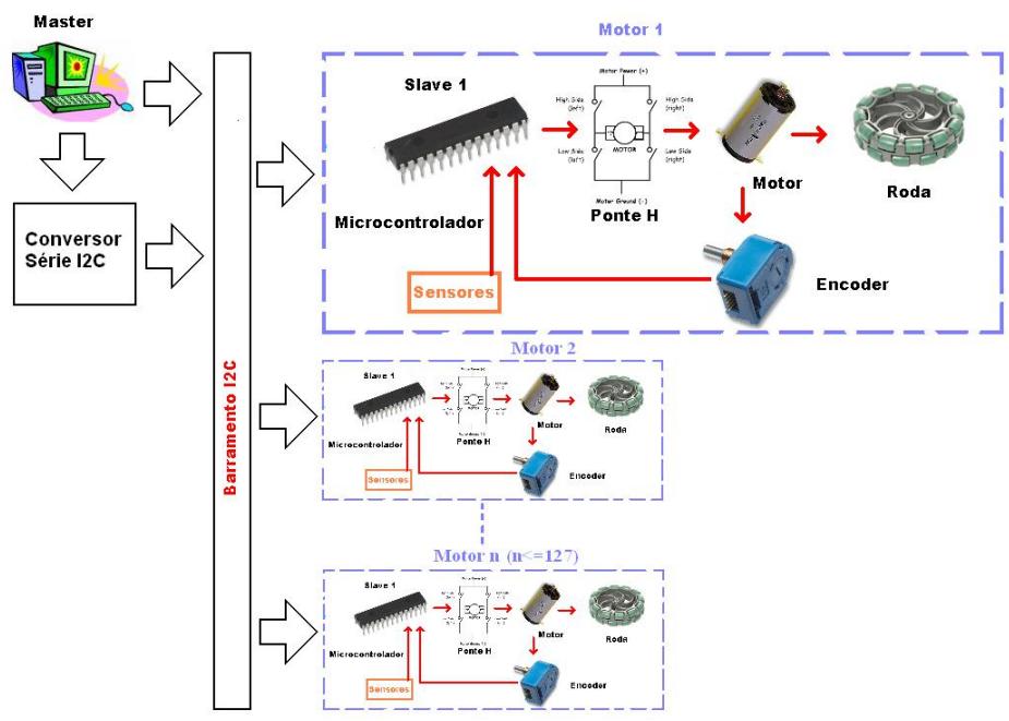
Since the whole robot hardware communicates using I2C, this driver was developed with the same protocol and therefore it connects to the main system via an I2C connection and commands are exchanged continuously to permit a "keepalive" state of the circuit board. The absence of communication between the main system and the motor driver leads to an instantaneous motor halt to avoid hypothetical robot collisions. This motor driver is also enabled to control several different aspects of the system from motor and system temperatures from different sensors, voltage sensors, encoders, PWM, power management, self calibration, etc. The I2C commands also permit system telemetry and actions can be taken by the main system in case of anomalies detected from the readings.
The overall cost of building this driver system was meant to be low thus defining the criterion on the component selection. This in turn had to be aligned with the choice for updated components to avoid lack of future supply. The driver was designed to control a single motor/encoder. For the three motors of the robot it is necessary three motor driver boards. Fig. 4 shows a picture of the actual motor driver board developed.
As it can be seen from Fig. 4, the board is divided in two parts with separate boards:
- a) The brain part
- b) The power part
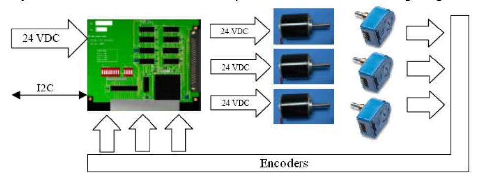
This allows a quick replacement of either board in case of failure. The brain part is the small board where the I2C bus and controller is located (left on Fig. 4). The controller is programmable and therefore its firmware can be upgraded at any time. The power part (right on Fig. 4) contains the H-bridge, voltage converter, ADC for various purposes, temperature sensors, etc. Due to the high power heat dissipation, a fan and heat sink were also installed. The fan speed is monitored and controlled by the system. In normal operation, the main system essentially sends angular speeds for each motor driver to control the robot thus relieving the robot's main processor from other motor driver tasks. The system is based on a feedback loop as shown on the following diagram:
It should be considered that the single board shown in the picture represents the three boards needed to operate the robot. As a more detailed functional diagram the following picture reflects the actual system.
Some of the I2C commands exchanged between the main system and the board are shown on Table 1. Table 2 describes the board physical and electrical specifications.
The board allows the setup of many parameters in order to properly control the motors, and the most important are described on the following table.
![Minho motor driver [5]](/tdps/soccer_midsize__2009__Minho/_page_3_Picture_6.jpeg)
List of some I2C commands exchanged between the main system and the motor driver board
| Code | Command | Description |
|---|---|---|
| 0 | MTR_ADRS | Motor driver address |
| 1 | MTR_FLAG | Motor presence flag |
| 2 | KP | PID control – Proportional |
| 3 | KI | PID control – Integrative |
| 4 | KD | PID control – Derivative |
| 9 | AMP_LIM | Máximum motor current |
| 10 | VOLT_LIM | Minimum H‐Bridge working voltage |
| 11 | TEMP_P_LIM | Maximum H‐Bridge temperature |
| 12 | TEMP_M_LIM | Maximum Motor temperature |
| 13 | PPR_ENC | Encoder pulses per evolution |
| 25 | PWM_FREQ_M | PWM Oscillation Frequency |
| 28 | CRISTAL_H | Microcontroler Crystal Frequency |
| 30 | BRAKE | Signal for forced or free brake |
| 31 | VEL_DES_M | Motor Speed |
| 33 | VEL_ACT_M | Actual Motor Speed |
| 35 | AMP_ACT | Actual Motor Current |
| 36 | VOLT_ACT | Actual H‐Bridge Voltage |
| 37 | TEMP_P_ACT | Actual H‐Bridge Temperature |
| 38 | TEMP_M_ACT | Actual Motor Temperature |
Motor Driver Board Physical and Electrical specifications
| Description | Value | Unit |
|---|---|---|
| Input Voltage | 17…35 | V |
| PWM Frequency | 19500 | Hz |
| Nominal Current | 18 | A |
| Standy Current | 110‐160 | mA |
| High Logic Level Voltage | 2…5 | V |
| Low Logic Level Voltage | 0…0,8 | V |
| I2C baud rate without converter | 100 | kbps |
| Working Temperature | 0…70 | °C |
| Maximum Temperature | ‐20…80 | °C |
| Dimensions | 80x160 | mm |
| Weight | 178 | g |
| I2C Serial Converter Nomival Voltage | 5 | V |
| Nominal Current | 6 | mA |
| I2C baud rate with converter | 2350 | bps |
| RS232 baud rate | 19200 | bps |
| Dimensions | 42x85 | mm |
| Weight | 23 | g |
4. Vision head
Minho team robots have also seen improvements on the robot's sight. The old vision head (camera + mirror) can be described on [6]. Like many other teams, these robots use a single camera pointing upwards onto an omnidireccional mirror. The mirror projects the environment all around the robot onto the camera lens. This means that the mirror, camera and lens have to be selected in order to take the most out of the three devices, in order to capture as much as possible from the surrounding area. Field localisation is achieved mostly based on vision and hence, field lines are essential for this process to be successful. Also, the other robots (as obstacles) and the ball have to have a clear sight to avoid collisions or time waste searching for a ball respectively.
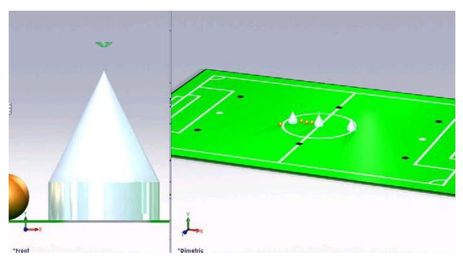
New technologies were used such as a CAD/CAM to model the mirror. This technique allows a simulation of the real game field when a camera and mirror is positioned accordingly in relation to the virtual world. The obstacles and the ball can also be easily simulated to get a perspective of the robot's vision in a virtual scenario. To achieve the best performance, the mirror has to be in conformity with the vision needs by reflecting the right amount of surrounding area, not more nor less. Its angle of inclination at 360º should provide enough visibility to see a complete field from its centre. Being made of highly polished stainless steel, the mirror size matters due to the weight exerted on the pillars that form the robot's head.
Fig. 7 and Fig. 8 show images from the CAD simulation. The drawings are at 1:1 scale and it can be seen the proportions of the regulated game field size versus the ball and robots (Fig. 7). The mirror is located above the tip of the cone representing the robot on the left side of Fig. 7. Since an elaborated robot was not necessary for this simulation, they were represented by a cylinder followed by a cone. It accelerates the rendering time. As with the ball, the same principle was followed. The game field is a 18m x 12 m defined by the Robocup rules for 2009. An advantage of simulation is the easiness of changing the positioning of the different components (robots and balls) and also the light variation to test different illumination scenarios.
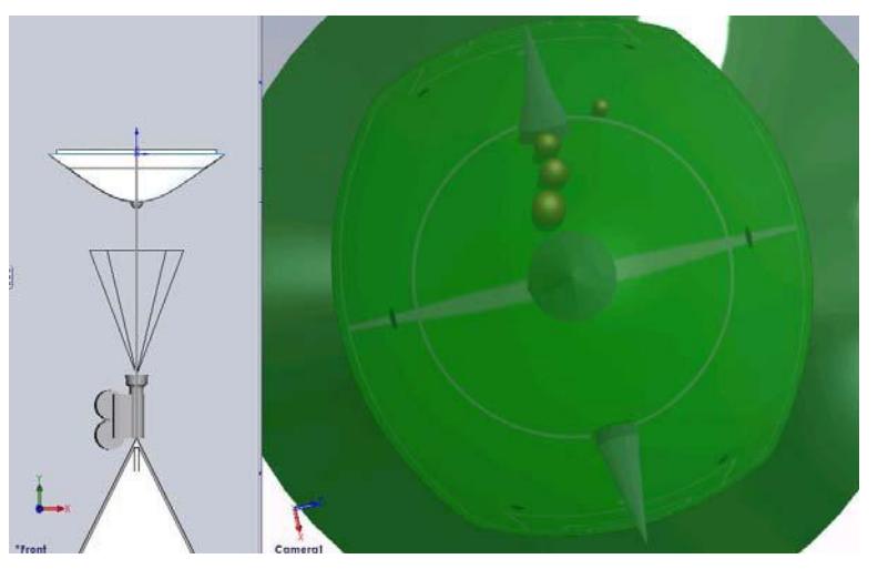
Fig. 8 (left) shows the mirror development defined by its contours and respective camera viewing angle and positioning. The mirror contours are defined by splines defined by vertices and curves with known radius. The CAD then revolves the spline along a vertical axis around 360º to make the "solid". To this 3D shape a glass mirror texture is applied allowing the camera to render the virtual reflections caused by the mirror curvature. This solution is based on a trial and error system with advantages to typical optical geometry calculations since the light factor is also computed in this case. By changing the splines and rendering the new image, one can see in a matter of seconds what the new image will be.
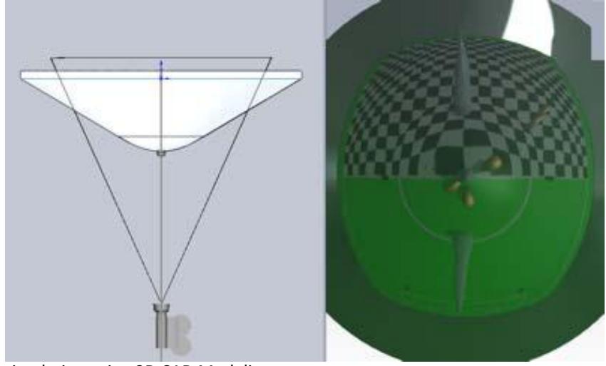
Fig. 9 shows another example of the mirror development but this time half of the game field was replaced by a chess board pattern with 50 cm side squares, in order to allow the viewing of zooming and distortions, far viewing and self viewing of the robot. As it can be seen on the picture, the whole game field (18mx12m) can be seen with the robot positioned in the midfield.
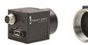
The robot camera was also upgraded to improve image quality and frame rate in a small form factor. Point Grey Research Inc. has a line of Firewire 800 cameras named Flea2 that presents interesting features for a very small lightweight camera. These colour cameras comprehend a 9-pin IEEE-1394b 800Mb/s interface, a Sony 1/3" CCD sensor able to produce VGA 640x480 video and a frame rate up to 80 fps. It also allows on-camera image processing such as conversion to YUV411, YUV422 and RGB formats, continuous static image for testing and development, control of sharpness, hue, saturation, gamma. Camera dimensions are 29 x 29 x 30 mm and are ready for C-Mount lenses. Fig. 10 shows images of this small form factor camera.
For the simulated mirror a set of different lenses was tested and a 4.5 mm C-Mount lens with F1.4 was chosen due to produce the best image result with the developed mirror.
The CAM processing was made directly from the CAD drawings. G-Code generated by the software package used was adapted to the CNC machine that lathed the stainless steel rod. This process guarantees that each mirror is produced systematically and with the same shape, up to the micron. Polishing is needed at the end in order to produce the mirror finishing.
5. Changes in the software code
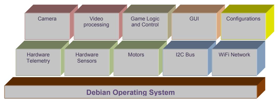
The Minho team robot software has its source code written in C++ on QT running on a Debian Linux based Operating System. The new source code was ported from the old system and new classes and objects were defined with the code completely re-written.
A new structure and class hierarchy was defined separating the hardware classes in charge of managing the different hardware signal sources, from the control classes, network classes, vision classes and the game logic and control classes. This new structure allows the test of each individual class separately and isolates the inherent problems, features and behaviours typical of each class. Fig. 11 shows the class diagram defined for the robots.
5.1 Image Processing
The image processing analysis is carried out in two phases:
The first one corresponds to the parameters setup. It consists of creating a look up table (LUT) with the memory addresses of each pixel on the image to analyse according to a predefined mask.
In parallel with this LUT, another one is created which stores the real distances (world coordinates) of each pixel to the centre of the image and to the centre of the robot.
The second part corresponds to the treatment of the grabbed image. The whole image is converted from 3 bytes to 1 byte per pixel, becoming a smaller image to analyse and easy to process. The used method to differentiate each byte consists is dependent on a typical colour calibration using another Look up Table.
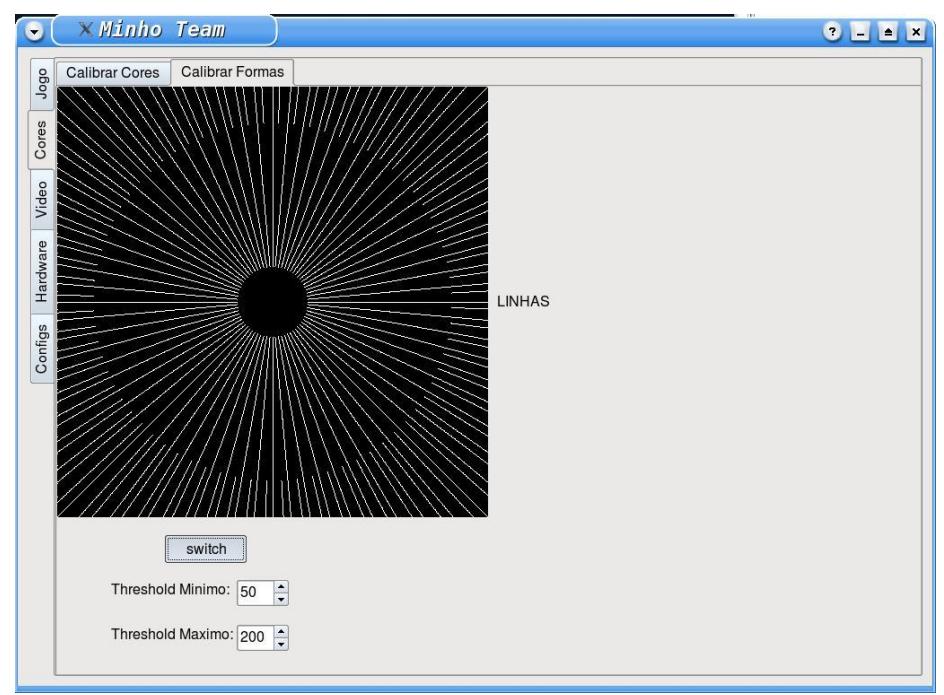
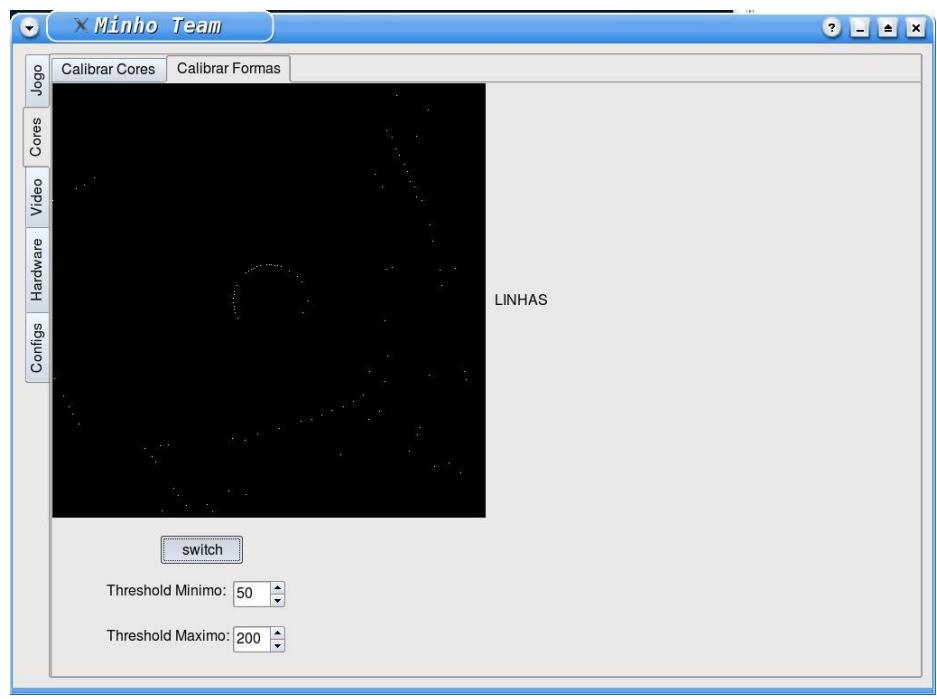
This grabbed image (1 byte per pixel) is not fully analysed, just the pixels represented by the mask on Figure 12, from the centre of the image towards outside. The task consists of finding transitions between green and white, storing only the pixels where that transition occurs. The next figure shows an example of such a result, from an image taken at our laboratory.

5.2 Localization
This team already developed a localization algorithm described on [7]. For this new generation, some relevant changes have been implemented.
First, a virtual field is created in memory (720x480), in which each byte represents 2,5cm2 of the real field. This virtual field contains '1' where field lines exist and '0' where it does not exist. As an example, the corner of a field would be represented by the matrix below.
The next step consists of testing possibilities by fitting the coordinates extracted (figure 14) on the virtual field (figure 15).
For each trial an estimation of feasibility is calculated in order to choose afterwards the best solution, which will consist on the position of the robot. The number of iterations is cut down by using the electronic campus on the robot to tell its orientation.
After some well achieved and feasible localization calculations, only one part of the virtual field is searched for. This way the processor is released increasing the number of frames per second.
Look Up Table that represents the field in memory
| 1 | 1 | 1 | 1 | 1 | 1 | 1 | 1 | 1 | 1 | 1 | 1 |
|---|---|---|---|---|---|---|---|---|---|---|---|
| 1 | 1 | 1 | 1 | 1 | 1 | 1 | 1 | 1 | 1 | 1 | 1 |
| 1 | 1 | 1 | 1 | 1 | 1 | 1 | 1 | 1 | 1 | 1 | 1 |
| 1 | 1 | 1 | 1 | 1 | 1 | 1 | 1 | 1 | 1 | 1 | 1 |
| 1 | 1 | 1 | 1 | 1 | 0 | 0 | 0 | 0 | 0 | 0 | 0 |
| 1 | 1 | 1 | 1 | 1 | 0 | 0 | 0 | 0 | 0 | 0 | 0 |
| 1 | 1 | 1 | 1 | 1 | 0 | 0 | 0 | 0 | 0 | 0 | 0 |
| 1 | 1 | 1 | 1 | 1 | 0 | 0 | 0 | 0 | 0 | 0 | 0 |
| 1 | 1 | 1 | 1 | 1 | 0 | 0 | 0 | 0 | 0 | 0 | 0 |
6. Conclusions
The Minho team started in 1998 and has been participating actively on RoboCup since then. The team builds a generation of robots and participates on competitions for a few years. Since the last two RoboCup competitions were outside Europe and the team budget is low, it was decided to build a new generation of robots: the 3rd generation. Therefore, many changes were implemented specially regarding the physical platform and some hardware. The software also suffered a big change not just on the tools used to program but also on the code itself. The robots are being tested and they are proving their feasibility. Due to lack of space, this paper describes only a few of those changes.
Acknowledgements
The team would like to thank the Algoritmi Research Centre, Department of Industrial Electronics, School of Engineering and University of Minho for all support. We also wish to thank Bruno Matos for his successful achievement on developing the motor driver for his Masters work. The Polymers Department and PIEP at University of Minho also deserve our thanks for all the support developing the robot physical structure in composite materials. The Mechanics Department allowed us to use their CNC machine in order to make the mirrors.
References
- New improvements of MINHO Team for RoboCup Middle Size League in 2003. F. Ribeiro, P. Braga, J. Monteiro, I. Moutinho, P. Silva, V. Silva. Pádua, Itália : Robocup'2003 – Team Description Paper, Julho 2003.
- Vickers Indentation Responses of Epoxy Polymers. I. M. Low, C. Shi. 14, 1998, Journal of Materials Science Letters, Vol. 17, pp. 1181‐1183.
- Ribeiro, F., Moutinho, I., Silva, P., Fraga, C., Pereira, N., "Controlling Omni‐ directional Wheels of a MSL RoboCup Autonomous Mobile Robot", Robotica'2004, April 2004, Porto, Portugal.
- Ribeiro, F., Moutinho, I., Silva, P., Fraga, C., Pereira, N., "Three Omni‐Directional Wheels Control On A Mobile Robot", CONTROL'2004 ‐ IMechE, IEE, University of BATH, Department of Mechanical Engineering, 6‐9 September 2004, Bath, UK, ISBN 086197‐ 130‐2.
- Matos, B. Controlador e Accionador para Motor DC em Malha Fechada. Guimaraes, Portugal : Master Thesis, Universidade do Minho, 2008.
- Ribeiro, F., Moutinho, I., Silva, P., Fraga, C., Pereira, N., "Vision, Kinematics and Game strategy in Multi‐Robot Systems like MSL RoboCup", ROBOCUP'2004 – Team Description Paper, July 2004.
- Ribeiro, F., Tosini, L., Lopes, G., "Localization of a Mobile Autonomous Robot Based on Image Analysis", IEEE – The 7th Conference on mobile robots and competitions, Abril 2007, Paderne, Algarve, Portugal.