Water Team Description Paper 2009
Xu Xiaofei, Wang Zhengguang, Zhang Jiexi, Wang Xueyuan, Zhao Liang, Liu Xiaoming, Xu Xinxin, Zhang Wanjie, Chen Song, Zhao peng, Zhang Lin, WangMiao, YinYue, Zhu Zhe, Wang Chenyu
Beijing Information Science & Technology University, China, 100192
Abstract The paper mainly introduces the hardware and the software control system of the robotic system built by the Water Team. The technology mainly include the design of the Omni-directional Vision System, Self-positioning System,the Robot Path Planning and Simulation.
Introduction
Water Team is a Middle Size robot team of Beijing Information Science and Technology University. This team was founded in 2003, and since then, has participated in the RoboCup China Open from 2006 to 2008.And won 2nd -place prizes in 2008. The team's major research areas are: Robot Vision, Software Architecture Frame of Component, Path Planning, Positioning, Forms of Communication and Control Models.
Hardware
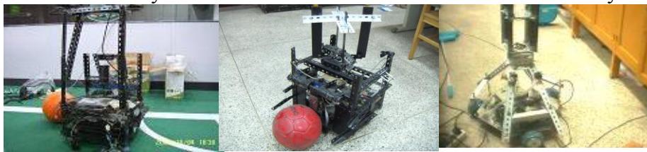
The original robot of Water was designed in 2003, and made manually by the team. The first two wheels robot was made manually by the team in 2006. Then in 2007 we made a large-scale transformation to it, and advanced the visual parts and motor driver parts of the robot. So the effect of the image and the speed of robot were upgraded.(Fig. 1 and 2)
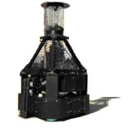
In 2008, our first Omni-directional three wheels robot was finished which was all made by ourselves. (Fig. 3) This robot was more
There are 4 subsystems in the hardware structure of our robot. They are the Vision System, Motion Control System, Decision-making system and Communication System.
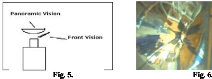
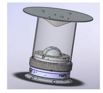
The Vision System includes 2 parts: the Panoramic Vision and the Prospect Vision. We designed our robot to use the same camera to collect the vision from the Panoramic Vision and the Prospect Vision. (Fig. 5 the design of the camera and Fig. 6 the vision effect in the camera) Fig. 4.
The Panoramic reflector was designed by ourselves. As the ball is the most important identification in the gaming court, the mirror needs to be designed to effectively identify it. The hyperbolic design for the omni-directional reflector makes the closer targets relatively large and farer ones (2 meters away) too small and hard to identify. The ratio of geometric design makes the close target too small and hard to identify. Therefore, we used the hybrid design in the omni-directional mirrors, so that all the targets can be able to be identified well. We use a Philips Camera with USB.
Our Omni-directional robot has three wheels, Compared with our robot in 2006. it can greatly improve the electrical efficiency. and three wheels make the camera steadier.
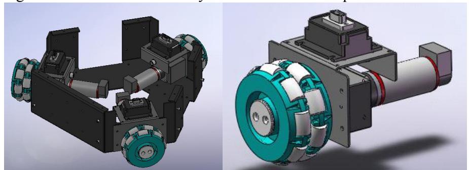
When we made the robot, we put an Omni-directional wheel, a 160w DC electric machinery and a pro-Motion BDMC3606SH Servo Driver together to make a Machinery Servo Driver. And placed them on the evenly Equilateral triangle robot machine chassis. The angle of the adjacent motor axis is 120 degrees. So the connection between the Machinery Servo Driver is simpler and easier to replace, remove or fix. (Fig. 7 and 8)
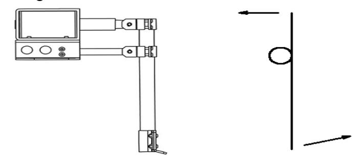
In our new robot, we used the Electromagnetic drive mode and the Leverage to make the shooting Agencies (Fig.9). In order to improve the driving force of Electromagnet, we designed a series of Step-up circuits, set the 24V to 380V, and stored the power in a Capacitor array. We tried to set the order by the discharging capacitor and convert the maximum possible electrical energy into the mechanical energy of hitting the ball.
According to the data of the experiment, when the shooting Agencies hit the ball, the height of the ball is about 1.2 meters and the distances are about 6.5 meters.
The Decision-making System and Communications System are the programs run on a laptop. The programs can receive the vision from the camera from the USB interface and make the decisions after analyzing the image. The Communication System also needs a wireless card.

Software System
We used C++ to write the coach program and the teammate program. The coach program is run in a laptop outside the field. And the teammate program is run in the laptop of our robots. In order to allow different models of machines to compete together, we use the C/S structure with the TCP/IP protocol for communication. The Coach laptop will be the Server and wait for the connection from the teammates. After the connection, the coach program will register a role for each of the robots automatically.
Based on the decision-making model, we wrote a program of environment Class. There are many Structures in the class, and these Structures will record the feedback data from each teammate. It includes self-positioning, the direction of the gate, the position of the ball, the position of the teammates and obstacles. When these data are updated, the Class will run the functions of the decision-making automatically, and calculate the data and performs the task based on the information.
The whole structure can be divided into 4 layers:
The Hardware Communication layer is the object used to communicate with the hardware devices. It includes a Serial Communication object to exchange the data with the robot subject. Video capture has a high demanding communication rate, and it connects by USB. So the object of the devices and the robot subject are divided.
The directive protocol layer is the core of the robot control structure, the object of the directive protocol is the code for the robot control. The function of this protocol is the exchange and analysis of the robot situation data and Sensors data from the robot.
The Action Layer consists of the objects of some abstract actions, these objects will send the control commands to the circuits of the robot by planning the local actions based on the sensors data from the protocol objects.
There are a lot of objects in this layer, but only one connection between the action objects and the protocol objects could be run. This is so it can avoid the chaos from multiple actions. The change in the robot action can be realized by the change to the connection with the action objects in the protocol layer. This operation can be made by the current action or by the decision layer objects.
The decision-making layer is the top layer of the robot. The object of the decision-making layer will organize the actions by the local sensors data, robot operational situation and the order data sent by the longdistance coach program. It can control the robot directly and also can control the robot action situation by changing the object of the action. For example, if the robot is looking for the something in the field, it will avoid the obstacles:
The coach program will send the aim location data to the robot local decision-making layer, the decision-making layer will pass the location data to the action object and connect with the object of the protocol layer, the object of the action will control the robot go to the aim location point.
When robot arrives at the location point,the first task ends. Then the action object will ask for the data of the second task, perform the second task and so on. When the robot meets the obstacle, the control of the robot program will change into the avoiding obstacle actions, after robot avoids the obstacle, the robot will continue going to the location point. And the action layer will divided into the different actions. the Omni-directional Vision System
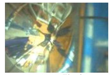
On the platform of the omni-directional, we use the panoramic mirrors, it can collect the big radius pictures. With the limitations of the machine production, the focal length of each robot is different. But we can adjust the focal length to solve this problem.(Fig. 10)
We use the USB camera to catch the Panoramic Vision and the Prospect Vision, within the framework of the DirectShow, we can get the 640*480, 30 frames per second vision streaming.
Color Threshold
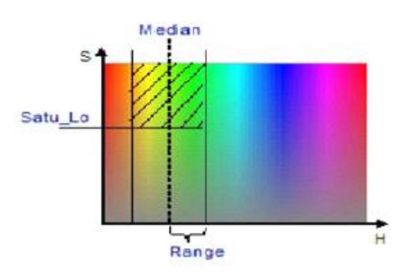
The robot uses the Color calibration method to find the target in the field. Our robot uses the USB Camera, outputs the image of 24 bit colors, it is very hard because of the color threshold, so we change from RGB to HSI and divide the colors
Within the character set of HIS the Color vector in H is a graded distribution, and the Color vector in S is from bright to dark.
Therefore, we are using the threshold range in the value and scope of the threshold of about two variables to define the scope of the threshold in the H vector, and in the S vector, we are using the minimum to limit the way to extract enough bright colors.
We get the image from the Panoramic Vision. We change the image from RGB to HSI and make them binaries. In order to remove the interference,we use erosion first, then diffusion on the pixels.
Target Recognition
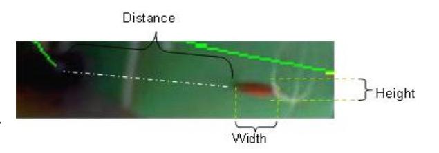
After dealing with the color, we get the shape of the target of the field. Because the image of the Panoramic Vision has some non-linear deformations , we do not know the easiest method to divide the items that have the same color as the target.
We build a Hash Table in which is recorded the the proportion of connected domain and the distance. When the robot finds the same color as the target. He will judge and compare it with the information in the Hash Table and then set the target of the region which matches the data in the Hash Table as the destination target of the robot.
Self-positioning
With the changes in the Middle Size rules, the ball will not have any color, so the robot needs the ability to self-locate. It will help the robot to make a decision when the robot know its location. Our robot self-locates by the white lines of the field.
Path Planning
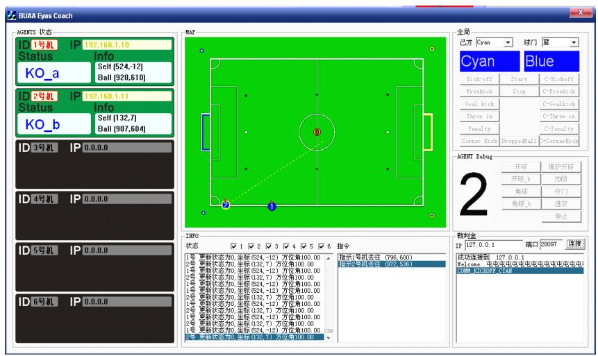
When the robot wants to go to the target point, he will perform some algorithms to find the best and the shortest way to go to the target. So he will search for the target when he does not know the target in the region first and build a point Collection A.{ a1,b1,c1 ……} And then search more regions from each point in Collection A, when the target points are covered in the search region of the robot.
The robot will calculate the path. Even if the there are some obstacles when robot searches for the target. The robot will find the best and the shortest way.
The multi-robot cooperation
Our multi-robot behaviour is based on the combination of the overall planning and conduct of individual autonomy. The off-site coach reacts on the change of the game state, searches the best solution from the preloaded database. At present, our communications infrastructure has stabilized after the testing. The solutions in the database are able to handle most of the normal situation in a competition. We are adding more solutions to the database to handle the unexpected situations.
Summary
The paper mainly introduces the hardware structure and the software systems of the robot system. The technology mainly includes: Omnidirectional Vision Design and Processing, Self-localization and Path Planning and Simulation. The paper describes the overall construction and processing methods used to design and build the Team Water robots.
Acknowledgement
The authors would like to acknowledge Zhao Liang, Wang Miao, Zhu Zhe, and Chen Song for their cooperation.
References
- Microchip. PIC16F87X DATA SHEET, 2001
- Microchip. MPLAB_ICD USER'S GUIDE ,1999
- Dou Zhenzhong. The Application Design and Examples of PIC. Beijing. Beijing University of Aeronautics and Astronautics Press
- http//www.Robocup.org.
- Li Shi, Xu Xuming, Ye Zhen, Zhang Zengqi. The International Robot Football match and Related Technology. Robot. 000,(9):420- 426.
- Team Description Paper 2005 CoPS Stuttgart T. Buchheim, U.-P. K appeler, R. Lafrenz, M. Oubbati, H. Rajaie, M. Schanz, F. Schreiber, O. Zweigle, and P. Levi ,2005
- Predicting away Robot Control Latency Sven Behnke2, Anna Egorova1, Alexander Gloye1, Ra′ul Rojas1,and Mark Simon1 ,2004
- Middle Size Robot League Rules and Regulations for 2005 Final Version 9.1 2005 0625 2005