Team Description Paper of Midlle Size Robots (ADRO 2010)
M.Taheri, S.H.Mohades Kasaei, S.M.Mohades Kasaei, M.Rahimi
Institute of Robotics and Intelligent Systems, Khorasgan Islamic Azad University, Isfahan, Iran
Abstract This paper wants to give a general description of Adro Middle Size League team for RoboCup 2010 competitions in Singapore. The Adro Lab mainly studies the cooperative team behavior in dynamic and uncertain environments. We have tried to focus on areas such as omni directional mechanism, cooperative behavior, world modeling, fuzzy decisions and behavior learning. This year, our developments for the Middle size league include: (1) The full design and construction of our new goalie and attacker robots. (2) The design and construction of a new hardware and software controller to be used in our robots. The project is described in two main parts: Hardware and Software. The software is developed in two major application, one is the server application which consists World Modeling, Global AI, Network and the second is a player application which consists robot self localization base on vision and electronic compass sensor, Network, local AI, Trajectory Planning and Motion Controller. The hardware consists of the robot itself and the driver circuit board. Each robot is able to pass, kick and dribble when it catches the ball. (3) The proposition of new methodologies to be used in the AI and vision system of our robots. The project is still in progress and some new interesting methods are described in the current report.
1 Introduction
Adro RoboCup team was established in 2005. Our team provides five robots of the same type and one goalkeeper robot with similar structure even though equipped with some additional accessories. Our aim is to have a cooperative team behavior while attaining a high individual robot performance in image processing, decision making and motion control. Some studied subjects in this work are: "Artificial Intelligence includes Fuzzy Decision-Making and Neural Behaviors Learning based on Strategy concept, Advanced Jacobean MIMO Controller, Image processing and high performance motor driver modules". We believe that a reliable mechanical structure design, robust pioneer algorithms and high performance sensor fusion are principles of a high team performance in MSL. The hardware of the robots (both mechanical and electrical) will be introduced first and a scheme of the module-based software diagrams and an introduction to its different units are considered afterwards. Focusing on the most significant research issues, an overall description of the team is presented here.
2 Hardware Architecture
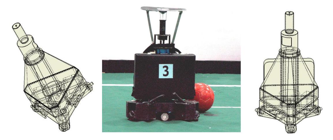
The robots' mechanics consist of a three-wheeled movement system, a kicker and ball handling mechanisms (Fig. 1). The wheeled movement system has three actuated wheels and each is driven by one DC motor. Having three independently controllable wheels, the robot can rotate or move in either direct or curved path. Using this system, robot can reach a maximum speed of about 2 meters per second. The kicker's operation is based on a solenoid, which is fed utilizing a boost circuit (with an approximate voltage of 400 volts). Almost all participating robots which designed based on this system can be only commanded with a constant power to shoot the ball. Since the power of their solenoid kicking system is calibrated for the maximum velocity of ball, it can be used only for shooting to the goal with a certain power but can not be used for passing the ball. The advantage of our robots is their adjustable and strong kicking device therefore the robot is able to throw a controlled loopshoot toward the opponent goal before the opponent defender can reach it. A circuit is designed and used to generate different currents for solenoid to have different powers of shooting. Each robot has six DC motors (three for driving wheels and three for ball handling which are driven by two drivers that are placed on the robot's main control board. The main board uses AVR microcontrollers as a digital processing unit that enables the robot to have some onboard processing. The program for the microcontrollers is written in AVR C language.
3 Robot Software
This section describes the main software components of the robot system.
3.1 Image processing algorithm
Utilizing a camera, each time the computer on each robot performs the processing of the current frame and calculates the position, direction and velocity of the robot. It also determines the position and velocity of the opponent robots as well as the position and velocity of the ball. The image-processing algorithm first filters the image by using a table for labeling the colors then recognizes the contiguous regions through either a BFS or a DFS search algorithm and finally extracts the positions by looking in the Image to ground map table. The server gives the necessary commands to the image processing computers. The algorithm used to find objects is optimized to process the maximum number of frames. First it searches the pixels by swiping them with certain steps, when it finds a desired one and detects that object, saves its coordinates so the next time it can start back with the same point about. Sometimes for better image manipulation the RGB color space is converted to HLS (Hue, Saturation and Luminance). To recognize a certain color, a combination of conditions on Hue, Saturation and RGB is used. This procedure makes the color recognition independent from the change of brightness and other unpredicted conditions. We are trying to evaluate new methods to find some kinds of objects based on pattern recognition to reduce the effect of changing the colors on algorithm. The image processor receives its data through fire wire port connected to a Basler digital video camera with the speed of 20 to 30 frames per second.
3.2 Network
The network physical layer uses the shunted ring topology. The UDP (User Datagram Protocol) network protocol is used for the software communication layer. The data flow of the network is as follows: A half field data (the data representing the position and status of the robots, opponents, goals and the ball) is transmitted to the server from each client computer of robots, the server combines them, constructs the complete global localization field then sends the appropriate data and commands (indicating which objects each robot should search for) back to the clients. When the data is completed it is passed to the AI unit for further processing and to decide the next behavior of the robots.
3.3 Artificial Intelligence
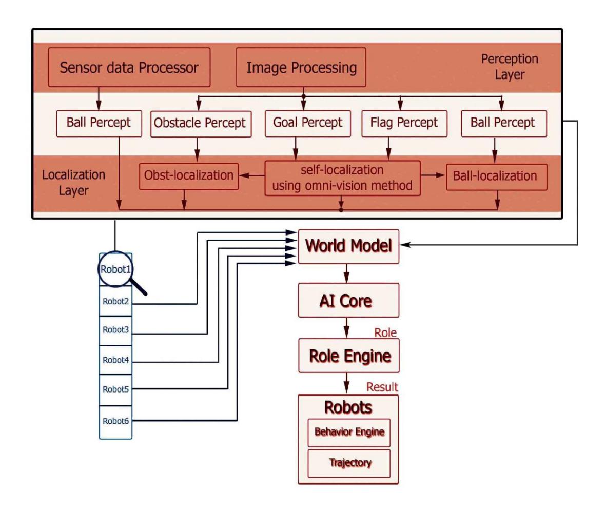
In this section the AI part of the software is briefly introduced. There are three distinct layers: AI Core, Role Engine and Behavior Engine. AI Core receives the computed field data from World Map Modeling unit and determines the play state according to the ball, opponents and our robots positions. Considering the current game strategy, determination of the play state is done by fuzzy decision-making to avoid undesirable and sudden changes of roles or behaviors. Then AI Core sends a set of roles to Role Engine to be assigned to the robots. Because there are instances in which the image-processing unit cannot see the ball, a memory is implemented in the AI Core for the position of ball that specifies which robot owns the ball. Since there is a relationship between new roles and old roles, roles are changed in a manner that robots never experiment sudden changes in roles (for example the role never changes from defense to attack in next cycle). Role Engine receives a set of roles from AI Core and provides the Behavior Engine with a set of behaviors for robots. Twin or triple roles are implemented so that the robots really cooperate with each other to do their roles. Behavior Engine receives an array of behaviors from Role Engine and then according to the allocated behavior each robot must execute commands, with the help of Trajectory Unit, it sets the control inputs for the controller. It should be noted that the behaviors are learned offline so that they can provide a wide range of flexibility in a certain behavior (Fig. 2).
3.4 Trajectory
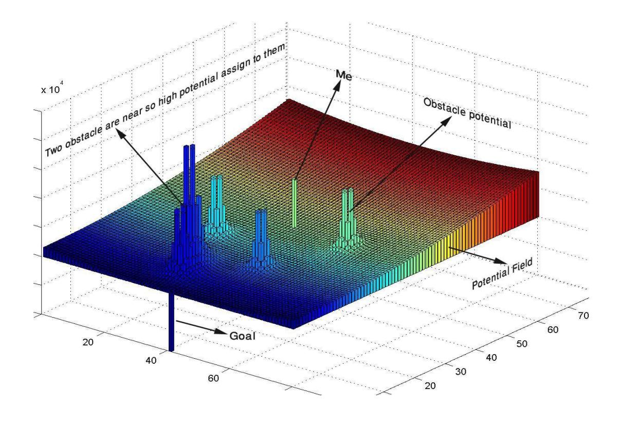
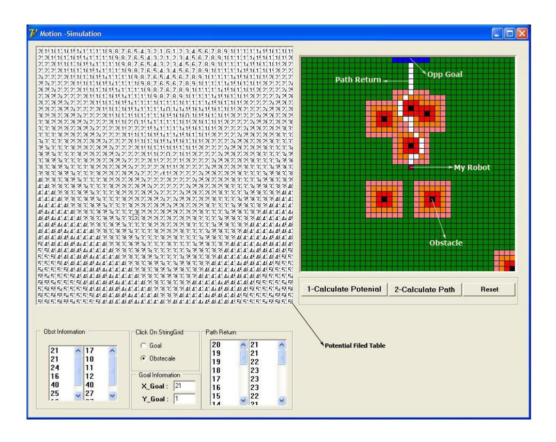
Since the motion trajectory of each robot is divided into several median points that the robot should reach them one by one in a sequence the output obtained after the execution of AI will be a set of position and velocity vectors. So the task of the trajectory will be to guide the robots through the opponents to reach the destination. The routine used for this purpose is the potential field method (also an alternative new method is in progress which models the robot motion through opponents same as the flowing of a bulk of water through obstacles). In this method different electrical charges are assigned to our robots, opponents and the ball. Then by calculating the potential field of this system of charges a path will be suggested for the robot. At a higher level, predictions can be used to anticipate the position of the opponents and make better decisions in order to reach the desired vector (Fig. 3).
3.5 Controller
So far we have reached a point where the trajectory has calculated a path in conjunction with the destination velocity vectors. If the robot moves on this path, it will reach the destination with no contact. Due to the non-symmetric nature of the wheeled movement system and different frictional forces in the wheels, we can't rely on exact operation of this open-loop system. Therefore, it's required to use a controller with a proper feedback to produce the correct control signals for the wheels of the robot in order to move accurately through the path. The movement system has three parameters that are the motor power (which is represented here by PWM) of the three wheels. Controlling the position of robot is done by using a PC-Based PI controller on velocity that obtains its feedback from three encoders located on the bisector lines of the motor line angles. The robot position is calculated via inverse kinematics method then the controller calculates necessary virtual forces (Fx, Fy) and moment (M) to reach the desired velocity vector and orientation. Finally in a forward dynamic algorithm the appropriate PWMs are obtained and applied to the motors. The algorithm was described here called Jacobean based MIMO controller which changes the controlled system variables (angular velocity of motors) into more visible ones (linear and angular velocity of the robot). Then by utilizing a PI SISO controller and calculating the required values, it changes the outputs in a way to be applicable to the system .The controller always modifies the orientation and velocity of each robot to the value given by trajectory unit.
3.6 Self-Localization
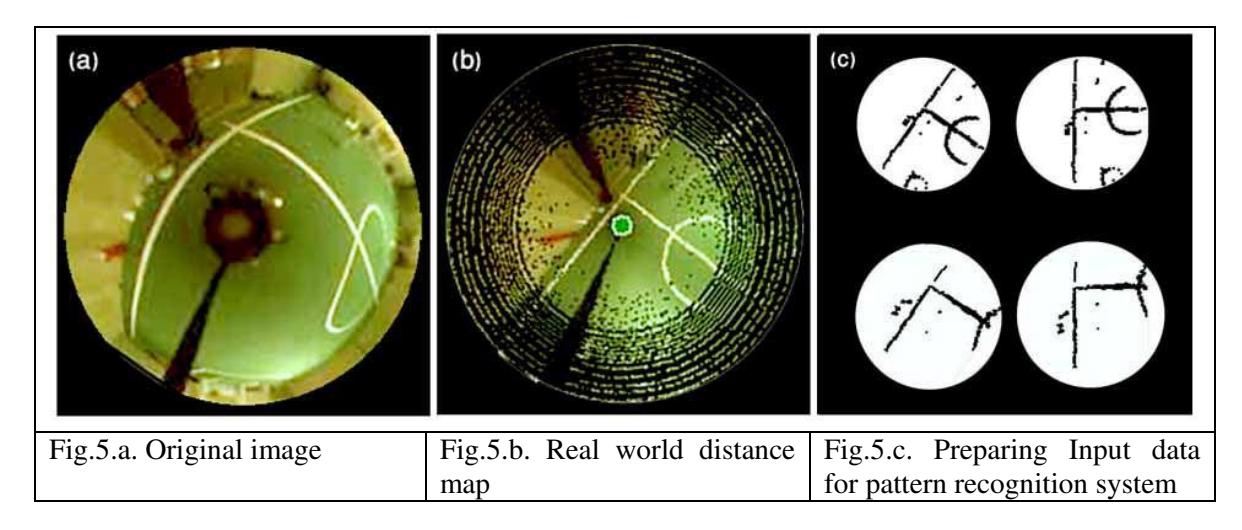
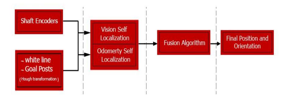
Our self localization method is based on detection of white lines in field. Because according to MSL rule no flag and no color goals exist in field since Robocup 2008, now the white line points are the only visual information that could be used as landmarks for robot's selflocalization. So our vision system tracks all white lines that exist only in the region field color (green) and robots use a digital compass (MTi-sensor) for the robot heading reference. After this section we try to convert the acquired white line point into the real world distance map and we employ a pattern recognition system (Fig. 5).
4 Conclusion
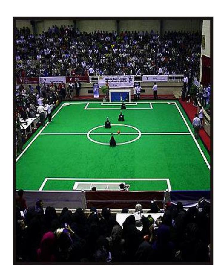
In this paper cooperative behavior, Condition Monitoring,, world modeling for an autonomous omni-directional mobile robot is presented. The main trust of our research has been put into developing reliable and fast soccer robots for environmental dynamic monitoring. Combination of odometry and vision led to a more accurate and reliable selflocalization algorithm. The performance of our robots team in RoboCup competitions showed that the combination of methods and techniques described in this paper are led to a successful autonomous robot and soccer player team (Fig. 7). The basis for our researches was the robust and reliable hardware design, the well-structured software architecture and efficient algorithms for sensor fusion and behavior generation.
References
- Burdick, H.E. Digital Imaging theory and application. McGraw-Hill, NewYork, 1997.
- H.J.Zimmermann, H.J.Zimmerman. Fuzzy Set Theory and its Applications. Kluwer Academic Publishers, 4th Ed. 2001.
- Ripley, B.D. Pattern Recognition and Neural Networks. Cambridge University Press, 1996.
- Keigo Watnable, "Control of an Omnidirectional Mobile Robot", Second International Conference Acknowledge-Based Intelligent Electronic Systems,21-23 April
- Cantu, M. Mastering Delphi 6. Sybex. Inc, 2001.
- G.Weiss. Multiagent systems. A Modern Approach to Distributed Artificial Intelligence. MIT Press, 2000.
- S.J.Russell, P.Norvig. Artificial Intelligence: A Modern Approach. Prentice Hall, 2nd Ed 2002.
- R.R.Murphy. An Introduction to AI Robotics. MIT Press, 2000.
- P. Amini, M. DaneshPanah, H. Moballegh "A New Odometry System to Reduce Asymmetric Errors for Omnidirectional Mobile Robots"
- Fredric Chenavier,James L. Crowley: "Position Estimation for a Mobile Robot Using Vision and Odometry", Proceeding of IEEE International Conference on Robotics and Automation