Hibikino-Musashi Team Description Paper
Amir A.F. Nassiraei, Yuichi Kitazumi, Shuichi Ishida, Hiroshi Toriyama, Hirokazu Ono, Kazutomo Takenaka, Noriyuki Shinpuku, Masakazu Takaki, Yuichiro Fukunaga, Kota Yamada, Yasunori Takemura, Ivan Godler, Kazuo Ishii, Hiroyuki Miyamoto
Kyushu Institute of Technology, Japan; The University of Kitakyushu, Japan
http://hwm7.gyao.ne.jp/shinpuku/ · http://www.er.ams.eng.osaka-u.ac.jp/robocup-mid/index.cgi?page=Rules+and+Regulations · http://www.electrostatics.com/page2.html
Abstract This paper presents some of the technical elements of the "Musashi robot" developed for the RoboCup Middle-Size League. Since there are some solutions that are common to many teams, only the most recent developments and interesting research studies that distinguish our multi-robot system from others and show our contribution to improving Middle-Size League performance are presented. One of our research objectives is to investigate the proper solutions towards realizing the idea of the human-robot interaction in soccer. Three considerable topics that they can play significant role in this content are Robot-Reliability, Robot-Maneuverability and Robot-Human Safety. In the following sections, our approaches to realize this idea, in different and interesting ways, are presented.
1 Introduction
"Hibikino-Musashi" is a joint middle-size league RoboCup [1] soccer team funded in 2004 by three different research and educational organizations, all located in the Kitakyushu Science and Research Park, Kitakyushu, Japan. The team's main objective is to develop a competitive team of soccer-playing robots oriented to inspire the interaction of human-robot in soccer. In this direction three topics, Robot-Reliability, - Maneuverability and -Human Safety, are selected as the main criteria for the most research orientation and the robot development plans.
In section 2, after a short overview to the "Musashi" robot design principles and its modular hardware architecture (Robot-Reliability), the design concept and features of the developed three-directional goalie arm is described (Robot-Maneuverability). In following, the effect of static electricity to the robot motion caused by using the different materials for the robot wheels are evaluated (Robot-Reliability). Our recent studies on Robot-Human safety based on evaluation of the risk in MSL and the protective measure of Soccer-Robot are presented in section 3 (Robot-Human Safety). On the software side, our scientific innovation content on development of color recognition algorithm using Bio-Inspired Information Processing is presented (Robot-Reliability). The "Musashi" robot self localization method using MCL and dead reckoning and the features of the developed simulator are presented in section 4 and 5, respectively.
2 Hardware system
2.1 Musashi Robot Architecture and Specification
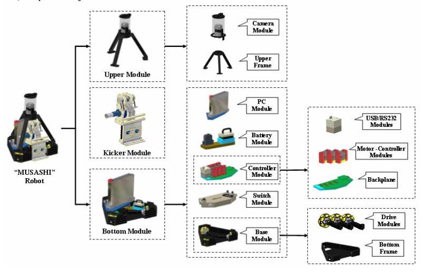
The current hardware configuration of the "Musashi" robot and its fully modular mechatronics architecture including an omni- directional moving mechanism and an omnivision system is shown in Fig.1 [2-4]. The modular robot architecture provides an effective way to improve reliability, robustness, ease of maintenance and transportation by decomposing hardware complexity into the smaller and compact modules. The robot is equipped with three 70 watts DC motor from Maxon, arranged in the shape of triangle. The maximum nominal motor speed of 7000 rpm is reduced through a planetary gearbox GP42 with the ratio of 12:1. The amplified mechanical torque on the output shaft of the gearbox is transferred to the wheel's shaft through the direct coupling and supported by a pair of the radial ball bearings with housing- T shaped type. The velocity feedback is done by using 500 pulses digital incremental encoders. The velocity of the wheels is controlled by three Faulhaber motor drivers (MCBL 2805), each equipped with a RS232 communication port. The controllers read the pulse trains from the motor encoders and produce PWM output voltages for the motors based on a PID algorithm. The result is a mobile robot with maximum linear speed of 2.4m/s and acceleration of 2.5m/s2
The only sensors using in the "Musashi Robot" are an omni-directional camera, a compass and three DC motor encoders. The electrical power is supplied by a set of Li-Polymer batteries (nominal voltage 25.9V/2Ah). The necessary required voltage for the camera, compass module and the micro computer power supply are produced by converting 25.9V to 12.0V and 5.0V. The power consumption of the robot is in average about 40W, and the operation duration of the robot is estimated to be 0.5h. In order to realize the shooting capability, the patented Cam Charger mechanism is introduced as a strong and compact kicking device. The key idea is to charge a series of strong torsion spring by using a special design of a cam in shape to shoot and lift the ball up to 6 m/s and 120 cm, respectively.
2.2 Development of the Goalie arm
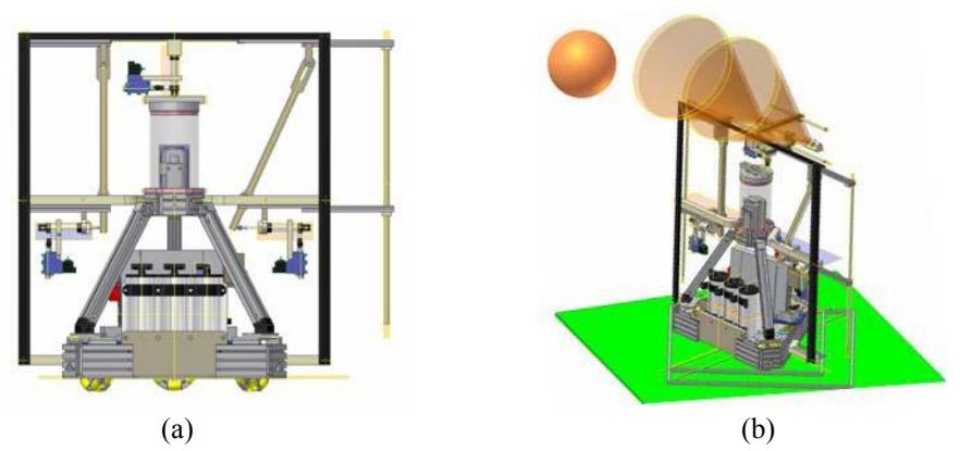
We developed an expanding arm for the goalie robot during this year's research. An important characteristic of the expanding arm is that it can expand the motion unit with a linear speed of 50-500 [m/s]. The speed depends on air pressure in the tank; therefore, it is also important to keep the air pressure in the tank at maximum level, to achieve good performance. The structure of goalie arm is constructed by air cylinders and solenoid valves. Motion units on both sides of a robot use air cylinder and the principle of leverage. The motion unit of expanding arm is guided by two sliders and shoots out straight to the side. Sliders for support are positioned one on top and one in the middle of the arm. Returning motion of an expanding arm is achieved by adjustable length rubber band functioning as a spring. The ratio of leverage in the expanding arm to generate enough motion by the air cylinder is 3 to 14[cm]. In the drawing shown in Figure 2-(a), the right hand side of expanding arm is extended and the left hand side is retracted.The upside expanding arm is directly powered by an air cylinder, and retracted by its own weight. Air pressure for the three air cylinders is supplied from three interconnected air tanks. The tanks provide air to the air cylinders. The pressure capacity of the three tanks is about 360[kPa].
PC on the robot and PIC program control the functioning of expanding arms on both sides. Based on the ball trajectory prediction, which is calculated on a PC, a signal to extend any of the two arms is sent to a PIC. The PIC controls the timing for retraction and inhibits the arm's functioning for a given period after retracting in accordance with the RoboCup Middle Size League Rule Book[5]. The upside expanding arm uses two ultrasonic sensors to detect an approaching ball as shown in Fig.2-(b). The arm is controlled by a PIC, and in accordance to the rules, inhibits the sensors' signal for a period specified in the rule book.
Advantages of the developed system are as follows:
- ・a goalie robot with expanding arms is more effective in blocking the ball comparing to a robot without the arms
- ・increased weight of a robot provides additional stability
- ・the upside expanding arm can block a loop shoot ball from above even in a retracted state.
Disadvantages can be recognized as follows:
・ expanding arms on both sides of a robot partially hide the white lines.
2.3 Relationship of the omni wheel materials and static electricity
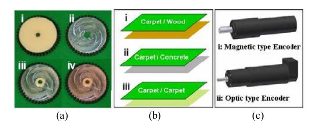
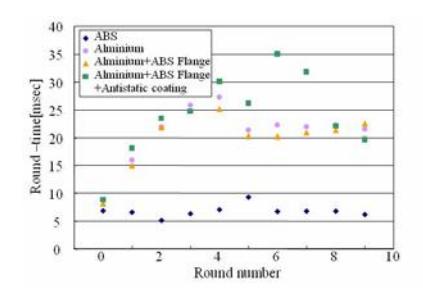
Static electricity refers to the build up of electric charge on the surface of objects. This simple and inadequate definition is of a phenomenon that creates problems which cost industry billions of dollars per year [6]. Static electricity is a problem that affects not only the robot computers, but almost can pose a constant danger to all electronics devices and sensors installed in the robot. In this section we investigate the effect of static electricity to the motor-encoder by evaluating the robot motion using eight different drive module combinations (four different types of omni wheels, derived by two different kinds of motor-encoder sets) and running the robot on three various environments (Fig.3). Robot is programmed to move along 1 meter square with the speed of 1.5 m/s. In case of no static electricity effect to the motor-encoders the time of each round should roughly be constant. For all 24 set of experiments, as illustrate in the Fig.4, the robot has the compatible and acceptable performance except three sets of experiments. As shown in Fig.5, when we are using ABS wheel with the magnet type encoder and running the robot on a carpet/carpet field the robot roundtime is almost remain constant (7 [sec]), but in case of using aluminum wheel the robot-round time increased almost 3 times more than the expected normal time. This caused by generating the static electricity on the surface of two connected carpets when the robot is moving on them. The generated static electricity is transferring through the aluminum wheel and the connected metal wheel-shaft to the encoder and in case of using a magnetic encoder static electricity seems to have direct effect on encoder pulse counting. As a summary of this section we propose two considerable criteria to design the safe and reliable drive unit: First the selected motor-gearhead combination must be including the optical encoder not magnetic type. Second, since the static electricity poses a constant danger to all electronics devices, we suggest that the robot wheel is made by plastic material rather than metal such as aluminum.
Results of 24 set of experiments
| a-i | a-ii | a-iii | a-iv | ||
|---|---|---|---|---|---|
| c-i | b-i | 0 | 0 | 0 | 0 |
| b-ii | 0 | 0 | 0 | 0 | |
| b-iii | 0 | × | × | × | |
| c-ii | b-i | 0 | 0 | 0 | 0 |
| b-ii | 0 | 0 | 0 | 0 | |
| b-iii | 0 | 0 | 0 | 0 |
3 Human-Robot Safety Concept
It is necessary that MSL obligates to give the security precaution to the robot of all team in consideration of the safety of all people who have the possibility of coming in contact with the robot. Based on our previous studies on reducing the risk through the riskassessment, and surveying of the critical hazard in other team's robots that could guide us to understand the present situation regulation regarding to the safety concept, in this section, we propose the new standard due to spreading the safety rules to the RoboCup Soccer Middle Size League.
3.1 Evaluation of the risk in MSL
Since the shape of the robots which participate in the competition differs depending on each team design criteria, as the current state, there is no common safety standard that all teams can be applied in their robots. In this direction, we focus attention on the robothuman collision, and we propose a new standard "Severity" which shows seriousness of dangerous by collision experiment.
To estimate "Severity" by the collision, the collision experiment is done with experimental instrument shown in Fig.6-a. We examine the relation of impact energy and the dent-amount of the clay when the pendulum collided with the clay. Here, it is assumed the energy which fractured the bone (8 [mm] in diameter) in the thigh part of the bird can be considered as a "Pain level" in case of the robot-human collision (Fig.6-b). Next, an attachment which has the same shape of the pendulum edge is mounted to the robot front to measure the dent-amount of the clay after the robot collided with the clay (Fig.6-c). TABLE 1 and 2 illustrate the result of collision experiment using the experimental instrument and the robot, respectively. The relation to the dent-amount of clay and the energy that the pendulum collided with the clay is the proportional relation, and can be approximated by equation 1.
$$Dent - Amount = 2.57 \cdot Collide - Energy$$
Based on the results show in the table 1 the pain level and the severity are 5.0 [J] and 13.66 [mm³], respectively. Consequently, the dent-amount of the clay when the robot collided with the clay while running with 1.0 [m/s] exceeded the "Severity" (TABLE 2). Therefore, 1.0[m/s] has possibility of giving harm in case of the robot-human collision.
TABLE 1 The result of collision experiment by the experimental instrument
| Energy [J] | 1 | 2 | 4.64 | 6.82 | 10.24 | 13.66 |
|---|---|---|---|---|---|---|
| Dent –amount [mm³] | 2.26 | 4.64 | 6.82 | 10.24 | 13.66 | - |
| Condition of the chicken-bone | No Fracture | No Fracture | No Fracture | No Fracture | Fracture | - |
TABLE 2 The result of collision experiment by the robot and the clay
| Robot speed [m/s] | 0.5 | 0.7 | 1.0 |
|---|---|---|---|
| Dent-amount[mm³] | 5.1 | 12.5 | 20.5 |
3.2 Protective measure of Soccer Robot
We added the cushioning material to the collision part; shown in fig.6-c, to evaluate the effect of the attached the material by the assessment experiment. TABLE 3 shows the relation between the number of the added cushioning material to the collision part when the robot collided with the clay with speed of 1.0 [m/s]. In this approach, as shown in the TABLE 3, the dent-amount of 11.9 [mm³] obtained by adding the two cushioning materials to the collision part of the robot is less than the measured 13.66 [mm³] "Severity" presented in previous section. The proposed method can be applied to evaluate the new rules regarding to adding 1 [cm] caution around the robot is sufficient for human-robot safety or not?
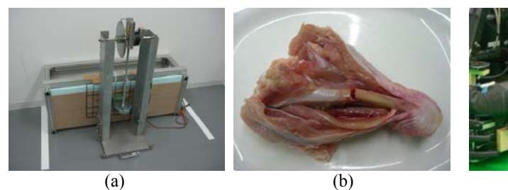
TABLE 3 The relation between the speed of the robot and the dent-amount
| Number of the cushioning material | 0 | 1 | 2 |
|---|---|---|---|
| Dent-amount [mm³] | 20.5 | 15.9 | 11.9 |
4 Software System
4.1 Color Recognition Algorithms using Bio-Inspired Information Processing
In this section, we introduce a color recognition algorithm based on bio-inspired information processing [7]; Self-Organizing Map (SOM)[8], Neural Gas (NG)[9], and modular network SOM (mnSOM)[10]. In RoboCup MSL, robots must detect an orange ball, green field, white lines and black robots. Our current vision uses two color models, YUV and HSV. The obtained images in YUV and HSV are binalized using thresholds to detect target colors, and logical AND of both images gives the target objects. The most important subject in color recognition is how to decide the threshold parameters. The proposed color recognition algorithm gives the threshold parameters in YUV and HSV spaces for orange, green and white. The input data to the color recognition system are measured reference colors (white, green, red, blue) of reference color board attached beside the omni-vision camera on the top of robot. The reference colors decide the operating environments of robots. The output data are thresholds to extract target colors. The color recognition system learns the input-output relationship between environments and thresholds using SOM, NG and mnSOM.
In order to evaluate the performance of color recognition algorithms, 15 sets of teaching data in various lighting conditions are prepared for learning. The teaching data are measured in fluorescent light, fluorescent light with sunshine, white mercury lamp, orange mercury lamp and under sunshine. In this time, the luminances of the environment change from 15 to 18640 [lx]. The 7 sets of data sets are used test data for performance evaluation, not used in the learning process. The learning times for each algorithm are 30000. Table 4 shows the comparison of the learning results. With 30000 times learning, the errors which means square of winner unit (module) vector and input vectors of SOM and NG based algorithms converged to almost zero, but in mnSOM algorithm still error remains. The executing speed means how fast can be processed online in our robot. The SOM and NG based algorithms can calculate almost twice faster than mnSOM based algorithm. Recognition rate indicates how many objects can be recognized in non-learning data sets. Regarding to the recognition rate, NG based algorithms show the best performance. mnSOM which is an expansion of conventional SOM shows also good performance. However, mnSOM needs calculation time includes the most complex of these algorithms. Therefore, NG algorithm can be recognized as the best algorithm of color recognition in our experiment.
TABLE 4 ENVIRONMENT OF THE NON LEARNING DATA
| SOM | NG | mnSOM | |
|---|---|---|---|
| Learning speed [sec] | 27.9 | 17.1 | 81.5 |
| Error of the learning data | 0.0007 | 0.0000 | 0.0367 |
| Execution speed [msec] | 61.3 | 58.4 | 114.9 |
| Recognize Rate of non learning data [%] | 83.3 | 85.4 | 85.4 |
4.2 Self Localization using MCL and dead reckoning
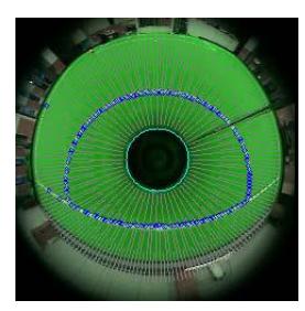
Our vision system uses omni-directional images in the YUV and HSV color spaces. We extract white and green from these images to avoid detecting white objects existing out of the field. To detect field lines, we scan the image using multi-layered scan lines arranged in radial direction and search the crossing points between the field lines and the scan lines. We use the MCL method which is one kind of particle filters for robot self localization. This method is used widely for mobile robot localization since it has good real-time performance and robustness. The field model is a Cartesian coordinate system with the origin at the center of the field in our algorithm. The robot state is represented by a vector $\mathbf{x}_t$ which consists of position (x,y) and direction $\theta$. We calculate the posterior probability distribution $p(\mathbf{x}_t | \mathbf{y}_1...\mathbf{y}_t)$ from the state of a robot $\mathbf{x}_t$ and the sensor data at $\mathbf{y}_t$ the current time t. In the particle filter, a probability distribution is represented by a set of N random samples. This method proceeds in two phases.
Prediction Phase: In the first phase we predict a current state of the robot. This is specified as a conditional distribution $p(\mathbf{x}t \mid \mathbf{x}{t-1}, \mathbf{u}{t-1})$ from the previous state $\mathbf{x}{t-1}$ and a control input $\mathbf{u}_{t-1}$. The predictive distribution is obtained by following equation.
$$p(\mathbf{x}{t} \mid \mathbf{y}{1}...\mathbf{y}{t-1}) = \int p(\mathbf{x}{t} \mid \mathbf{x}{t-1}, \mathbf{u}{t-1}) p(\mathbf{x}{t-1} \mid \mathbf{y}{1}...\mathbf{y}{t-1}) d\mathbf{x}{t-1}$$
Where $\mathbf{u}_{t-1}$ is the odometry data and it added to each particle.
Update Phase: In the second phase we update the distribution $p(\mathbf{x}_t \mid \mathbf{y}_1...\mathbf{y}_t)$ according to the sensor data. The likelihood of $\mathbf{y}_t$ at state $\mathbf{x}_t$ is represented as $p(\mathbf{y}_t \mid \mathbf{x}_t)$. The posterior distribution is obtained using Bayes theorem.
$$p(\mathbf{x}{t} \mid \mathbf{y}{1}...\mathbf{y}{t}) = \frac{p(\mathbf{y}{t} \mid \mathbf{x}{t})p(\mathbf{x}{t} \mid \mathbf{y}{1}...\mathbf{y}{t-1})}{p(\mathbf{y}{t} \mid \mathbf{y}{1}...\mathbf{y}_{t-1})}$$
Where $\mathbf{y}_{t}$ is distance to the field line. After updating the likelihood of all particles, they are normalized and re-sampled. Re-sampling proceed according to the weight of each particle: new particles are generated around the particles that have high likelihood.
There is possibility of failing in detection of direction because of the symmetric shape of the field, a direction sensor is implemented on the top of the robot.
5 Simulator
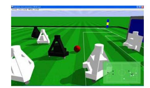
We developed a simulator which is integrated into the robot program this year. Before the game, we could debug behavior program (Fig.8). For instance, we could check the position of each robot in set-play or decide the coefficients of the function to calculate the path of dribble by trial and error in simulation environment. This simulator was developed with ODE (Open Dynamics Engine) and released as open source. More details can be found at http://hwm7.gyao.ne.jp/shinpuku/.
Acknowledgements
This work is supported by TOSHIBA Co and Meisenkai Co.
References
- H.Matsubara, M.Asada, H.Kitano, "History of RoboCup and Prospects of RoboCup-2002", RSJ, Vol.20, No.1, pp.2~6, 2002, In Japanese
- A.A.F.Nassiraei, "Concept of Intelligent Mechanical Design for Autonomous Mobile Robots", Kyushu Institute of Tech., Ph.D thesis, 2007
- A.A.F. Nassiraei, Y.Takemura, et. al. "Concept of Mechatronics Modular Design for an Autonomous Mobile Soccer robot", CIRA 2007, Jacksonville, pp.178~183
- A.A.F. Nassiraei, K Ishii, "How Does "Intelligent Mechanical Design Concept" Help Us to Enhance Robot's Function?," Intelligent Unmanned Systems: Theory and Applications, Volume 192, pp. 155-178, Springer 2009.
- RoboCup Middle Size Robot League Rules and Regulations for 2009 : http://www.er.ams.eng.osaka-u.ac.jp/robocup-mid/index.cgi?page=Rules+and+Regulations
- http://www.electrostatics.com/page2.html
- Y.Takemura, K.Ishii, "Evaluation of Color Constancy Vision Algorithm for Mobile Robots", C.S.Leung, M.Lee, and J.H.Chan (Editors), IEEE International Conference of ICONIP 2009, Part II, LNCS 5864, pp.409-419, 2009
- Kohonen, T.:Self-organized formation of topologically correct feature maps. Biol. Cybernetics 43, 59-69, 1982
- Mattinets, T.M., Berkovich, S.G., Schulten, K.J.: Neural Gas Network for Vector quantization and its Application to Time-Series Prediction., IEEE Transactions on neural networks, No.4, Vol.4, 1993
- K. Tokunaga and T.Furukawa, "Modular network SOM", Journal of Neural Networks, Vol.22, pp.82-90, 2009