Water Team Description Paper 2011
Min Huang, Xinsheng Ge, Shiyong Hui, Xueyan Wang, Song Chen, Xinxin Xu, Wanjie Zhang, Ye Lu, Xiaoming Liu, Liang Zhao, MiaoWang, Zhe Zhu, Chenyu Wang, Bin Huang, Libo Ma, Biao Qin, Fangyu Zhou, Changyun Wang
Beijing Information Science & Technology University, China, 100192
Abstract The paper mainly introduces the robot hardware and the software system of Water Team. The introductions mainly include hardware of robot, Vision System, Self-positioning System, the Robot Path Planning and multi cooperation
Keywords: We would like to encourage you to list your keywords in this section.
1 Introduction
Water Team is a Middle Size Robot Team of Beijing Information Science and Technology University. This team was founded in 2003. Water has participated in the China Open from 2006 to 2008. It won 2nd-place prizes from 2008 to 2009 and won the 1st-place in 2010. Water also participated in the RoboCup from 2009 to 2010, which got 7th and 1st. Water's major research focuses: Robot Vision, Software Architecture Frame of Component, Path Planning, Positioning, Forms of Communication and Control Models.
2 Hardware Structure
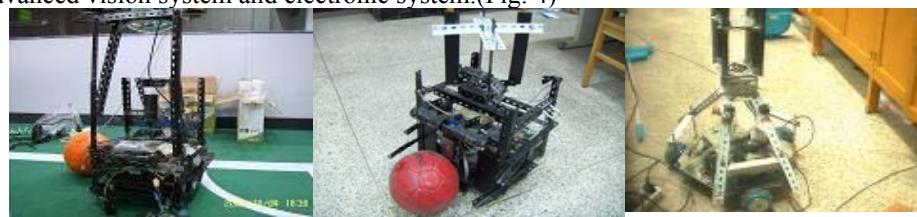
The original robot was made manually in 2004. The first two wheels robot was made manually by the team in 2006. Then in 2007 we made a large-scale transformation to it, and advanced the visual parts and motor driver parts of the robot. So the effect of the image and the speed of robot were upgraded. (Fig. 1 and 2) In 2008, our first Omni-directional three wheels robot was finished which was also made manually. (Fig. 3) This robot was more flexible.
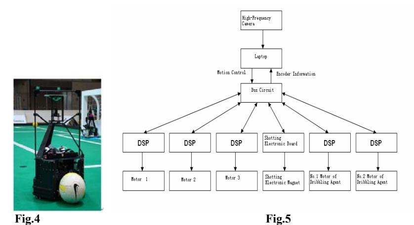
In 2009, our robot was advanced and new robot was born. In 2010, We use advanced vision system and electronic system.(Fig. 4)
The structure of hardware system (Fig.5)
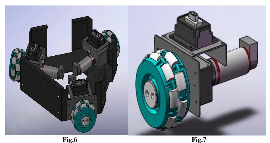
When we made the robot, we put an Omni-directional wheel, a 160w DC electric machinery and a pro-Motion BDMC3606SH Servo Driver together to make a Machinery Servo Driver. And placed them on the evenly Equilateral triangle robot machine chassis. The angle of the adjacent motor axis is 120 degrees. So the connection between the Machinery Servo Driver is simpler and easier to replace, remove or fix. (Fig. 6 and 7)
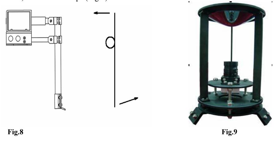
In our new robot, we used the Electromagnetic drive mode and the Leverage to make the shooting Agencies (Fig.8). In order to improve the driving force of Electromagnet, we designed a series of Step-up circuits, set the 24V to 380V, and stored the power in a Capacitor array.
According to the data of the experiment, when the Shooting Agencies hit the ball, the height of the ball is about 2 meters and the maximum distance is about 10 meters. We tried use the IGBT technology to control the energy and achieve the purpose of hitting the ball.
The camera of the robot is Point Grey, which interface:1394, image resolution: 640*480, frame rate: 60 fps.(Fig.9)
3 Software System
(No introductory text)
3.1 Vision
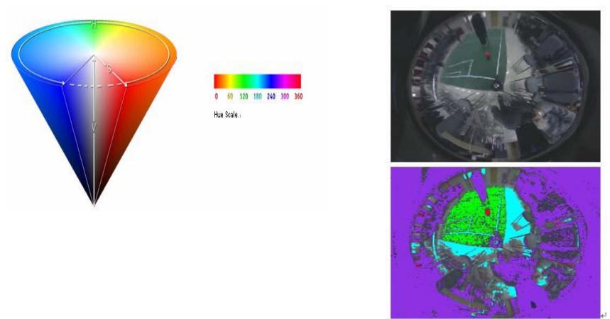
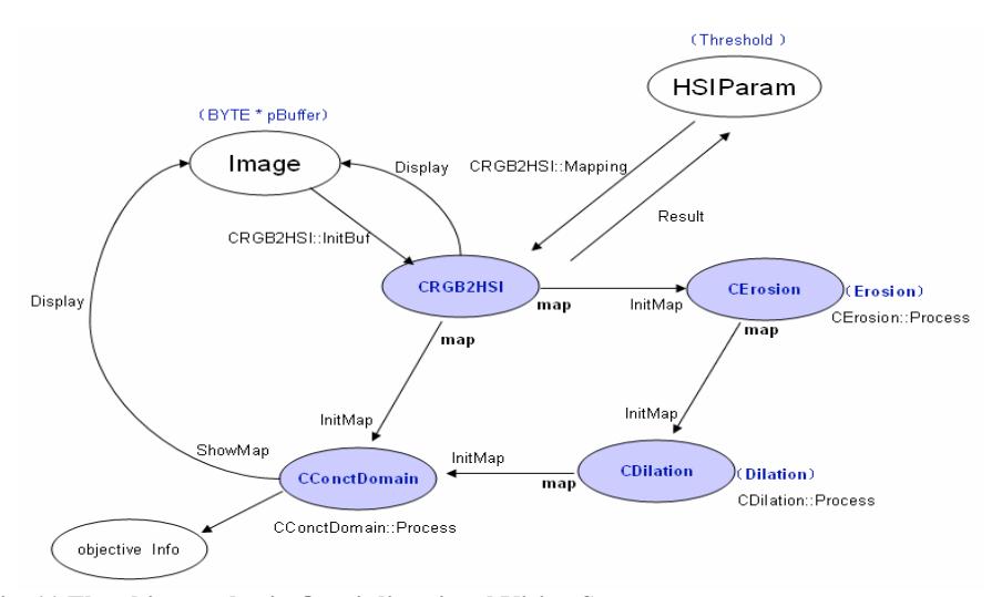
In the part of robot vision, we use HSV to describe the frame. With the distribution pixels of H, it judges the color of objects. The computer give the result of the binary. The football is red, the field is green, the field line is light blue and the obstacles are purple. (Fig.10, Fig. 11) The flow chart of vision system in software: (Fig. 11)
3.1 Self Positioning
Our robot self-locates by the white lines of the field relative to the position and angel of the robot.
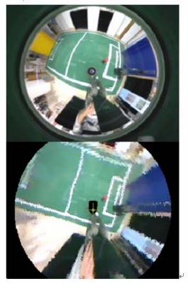
We will make correction to the omni-image first and recovery the shape of field line. (Fig. 13) The picture is Omni-image before correction and after correction.
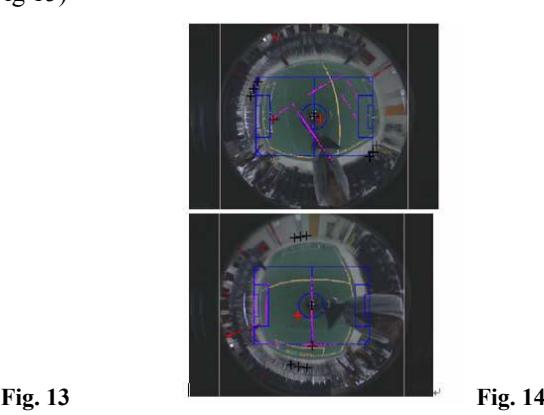
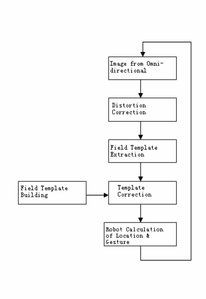
Through the white line in the image and template of field line, we get the location relative to the field line. From Fig 14, the color of template field line is blue. The white field line was expressed by pink matrix. The software will match the pink matrix with the blue lines until they get together. We calculate absolute coordinate in the field with the turning of matrix angel and distance.
The matching flow chat is: (Fig 15)
3.3 Path-Planning
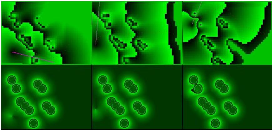
We use global decision to do the path-planning. This algorithm is similar with A* algorithm and reference the situation which the fluid was obstructed. It get real-time optimal path-planning.
This algorithm helps us to overcome the limitation of the dimensional grid and according to the result of path-planning we can control the robot and solve the problem with the dynamic obstacles.
3.4 Multi-Cooperation
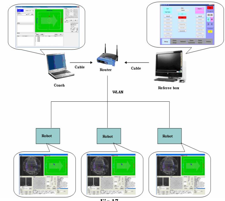
We use global planning and self decision to make robot cooperation. The Coach programming will analysis the match and give the direction from the referee-box. (Fig.17)
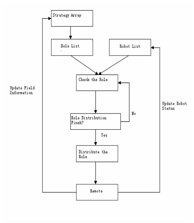
The flow chart of the rule distribution: (Fig.18)
4 Summary
The paper mainly introduces the hardware structure and the software systems of the robot system. The technology mainly includes: Vision Design and Processing, Selflocalization, Path Planning and Multi-Cooperation. The paper describes the overall construction and processing methods used to design and build the Team Water robots.
Acknowledgments. The authors would like to acknowledge Wang Miao, Zhu Zhe, and Chen Song for their cooperation.
References
- Microchip. PIC16F87X DATA SHEET, 2001
- Microchip. MPLAB_ICD USER'S GUIDE ,1999
- Dou Zhenzhong. The Application Design and Examples of PIC. Beijing. Beijing University of Aeronautics and Astronautics Press
- http//www.Robocup.org.
- Li Shi, Xu Xuming, Ye Zhen, Zhang Zengqi. The International Robot Football match and Related Technology. Robot. 000,(9):420- 426.
- Team Description Paper 2005 CoPS Stuttgart T. Buchheim, U.-P. K appeler, R. Lafrenz, M. Oubbati, H. Rajaie, M. Schanz, F. Schreiber, O. Zweigle, and P. Levi ,2005
- Predicting away Robot Control Latency Sven Behnke2, Anna Egorova1, Alexander Gloye1, Ra′ul Rojas1,and Mark Simon1 ,2004
- Middle Size Robot League Rules and Regulations for 2005 Final Version 9.1 2005 0625 2005