MU-Penguins 2013 Team Description
David Jahshan
Department of Electrical and Electronic Engineering The University of Melbourne Victoria 3010, Australia
Abstract Since MU-Penguins last appearance at Robocup in 2011, significant progress has been made in the robots hardware and software algorithms. The robot platform now consists of a 40mm diameter chassis housing two direct drive wheels, a unique rotating aluminium kicker arm in addition to multiple on board PCBs including an Altera Cyclone 3 based vision board and a Giada NI-HM76T nano ITX motherboard. The new motherboards support Intels i5 mobile dual core processors. This is a significant upgrade in computing power for each robot. The software architecture incorporates FPGA based parallel processed vision in addition to localisation, AI, motion planning and on board control.
Introduction
MU-Penguins primary aim is to develop robust robotic platforms to be used in more fundamental control and distributed computing research.
Hardware
The robots consist of a custom made chassis, a ball handle device with the ability to strike the ball, electrical payload and on-board image processing, communication and computation capabilities.
Chassis
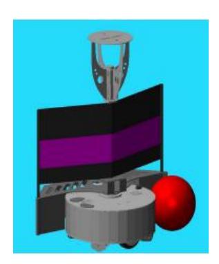
The chassis of the robot houses the battery, motherboard, electronic payload and wheel assembly for each device. The chassis consists of base plate and top plate that are connected together via the wheel housing to sandwich a 3mm foam coated tube of High Density Polyethylene. The base plate is an aluminium sheet 5mm thick and 40cm in diameter with four omnidirectional castors mounted equally spaced around the edge. On the top side of the plate, multiple PCBs are mounted including the main (or base) board and a nano ITX motherboard. The main board houses the motor control electronics and the Cyclone III FPGA vision processor. Next to the base board is the main processor, an Intel i5-3317U housed on a Giada NI-HM76T motherboard. Two 10mm aluminium uprights also attached to the base plate and provide support to the motors, pulley system and drive wheels. The robot is powered by a 5Ah 14.8V 15C Lithium polymer battery that is also mounted to this plate. Wireless antennae are also mounted to the base board and connect to the motherboard using a mini PCIe slot. The top plate consists of a 3mm aluminium sheet with a 40cm diameter. From the top plate a 20mm extruded aluminium tube is mounted vertically as a centre pivot for supporting the ball handling mechanism. There is a Lycra sail attached to increase the upper body width of the robot. On top of the tube is a camera mount with an Omni-directional mirror mounted at the top and the Jai CVA70 CL camera below [1]. The chassis currently weighs 10 to 12kg. It has a theoretical velocity of 5m/s and can accelerate at 3m/ss. The chassis is circular, with 40cm diameter. The total height of the robot is 80cm.
Ball Handling Device
The ball handling device consists of an aluminium assembly that can be rotated 360 degrees around the body of the robot with a slightly curved edge for controlling the ball. A kick is achieved by rotating the arm around the body of the robot and making contact with the ball. The outer shell of the chassis is used to ensure that the ball does not get wedged between the top and bottom plates. The kicker is mounted using spring loaded casters. These prevent warping of the aluminium tube and provide support to the kicker arm. The kicker arm is localised using a 7 bit optical encoder mounted to the top plate.
Electronic Payload
The electrical payload consists of 3 PCBs: the base board, a nano ITX motherboard and the FPGA vision processing board. The Base Board consists of three motors that are controlled by ST electronics VNH2SP30-E [2] fully integrated H-Bridge motor controller ICs. The motor controllers are coupled to an Atmel ATMEGA128 microcontroller [3]. Optical encoders are attached to the motors and kicker arm. This feedback is then fed into the microcontroller for low level odometry and control. Headers are provided to interface the vision processing boards to the microcontroller. USB is then used to communicate with the main processor. Main Processor. The main processor is Giada NI-HM76T nano ITX motherboard. It has an Intel i5-3317U dual core processor, and the usual assortment of I/Os expected on a PC. Attached to the motherboard is 4 GB of RAM and a solid state SATA hard drive. A 14.8v o ATX power adapter is used to power the Motherboard. Wireless is attached to the motherboard using an Intel 6200 Dual band mini PCIe wifi card. Vision Processing Board consist of an Altera Cyclone 3 EP3C25Q240C8 [4], two independent banks of 4 megabytes RAM and a Camera Link interface. A Jai CVA70 CL 60Hz 720 by 576 CCD camera [5] is used to capture and minimise the data transfer between the FPGA and main processor.
Software
The software is based around the original Unix philosophy of providing lots of small programs that do one thing well [6]. Each task is run as a daemon process. Each process writes its outputs to a file, which can be accessed by and may trigger other daemons. Each file is mapped to each other robot as required. This feature of the architecture ensures robustness. This structure also abstracts the complexities of multithreading to the operating system and permits the use of multiple programming languages.
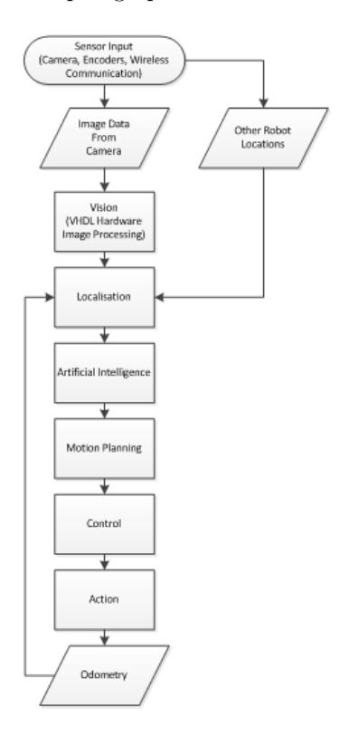
Figure 2 illustrates the high level overview of the architecture of single robot behaviour. A description of the major functions of the software is provided in the paragraphs below.
Sensor Input
The robot has three forms of sensory input: Camera, Motor Encoder and wireless communication. The camera allows the robot to see field markings, the ball and other robots. The motor encoders allow for relative movement information used in the systems odometry and the wireless communication allows for a global map of all robot positions to be generated by each individual robot.
Vision
The image processing is done on the Altera Cyclone 3 EP3C25Q240C8 to meet an upload frequency of 60 Hz for real time game play. Vision processing takes in the input pixel data from the camera and processes the data in parallel to provide compressed information for the on board localisation. Actions partaken by the FPGA include colour mapping of input pixels, image thresholding for the detection of objects such as the ball and field markings, and data compression for optimal pattern matching required for localisation.
Localisation
The localisation module uses vision data to generate a local map consisting of its own field position as well as the position of the ball and all other robots. The module subsequently generates a global map using sensor fusion of the odometry and local map information possessed by each robot on the team. Field localisation makes use of two techniques: The Hough transform and pattern matching. The Hough transform allows for a dominant field line to be detected within the series of point field marking features detected by vision. Once the dominant field line feature is detected, the pattern matching algorithm takes the dominant line feature and the rest of associated field feature data and searches against all the known line features of a soccer field that is stored in memory.
Artificial Intelligence
Artificial Intelligence takes in the robots state information (through the global map) and subsequently generates a target position and action for each robot. The module consists of three components: a set of predefined strategies, an evaluator and a rule checker. The predefined strategies generate a set of possible target positions using the game state and a set of mathematically defined objectives. The evaluator than evaluates each of the possible target locations, before assigning a weighting to each strategy, such that an ultimate target position can be determined via a weighted superposition. Finally, the rules checker ensures that the generated target position does not violate any robocup rules by nudging any violating robot away from an invalid region.
Motion Planning
The motion planning module generates a trajectory between the robots current position and the destination location generated by the AI module. Trajectories are generated using an extension of the potential flow based motion planning algorithm presented in [7], where the goal location is modelled as a sink and obstacles are used to model other robots and boundary regions. The output trajectory considers the non-holonomic constraint and actuation limitations of the MU Penguins platform by adding a source element to the potential flow algorithm and subsequently tuning the source and sink strength in order to satisfy kinematic constraints such as velocity and curvature. Trajectory generation is determined using a snapshot approach where a new trajectory is created at a fixed frequency fast enough to consider game dynamics and localisation uncertainty. The module outputs the position and corresponding velocity for the first step of the discretised trajectory as well as a desired kicker angle.
Control
The control module receives the desired kinematic data from motion planning and determines the necessary PWM command to actuate the motors. The control is implemented using both a position and velocity controller which work synchronously to keep the robot on its trajectory. Control on the base board and makes a PI controller and odometry for feedback.
References
[1] C. Marques and P.Lima, "A localization method for a soccer robot using a vision based omni-directional sensor," in Procs. of Robot Soccer World Cup IV, vol. 4, 2000. [2] St vnh2sp30-e automotive fully integrated h-bridge motor driver. [Online]. Available: http://www.st.com/stonline/books/pdf/docs/10832.pdf [3] Atmel atmega 128 microcontroller. [Online]. Available: www.atmel.com/atmel/acrobat/doc2467.pdf [4] Altera cyclone iii fpga family. [Online]. Available: www.altera.com/products/devices/cyclone3/cy3-index/jsp [5] Jai cv-a70cl. [Online]. Available: http://www.jai.com/EN/CameraSolutions/Products/Pages/CV-A70CL.aspx [6] M. Gancarz, "The unix philosophy," in Digital Press, 1994. [7] T. Owen, R. Hillier, and D. Lau, "Smooth path planning around elliptical obstacles using potential flow for non-holonomic robots," in Robot Soccer World Cup XV, vol. 7416, 2011.