ARES Team Description 2015
Xudong Liu, Jing Huang, Zhanxue Li, JiamingLi, YanLi, Ning Lu, XingruDong, JingbinYao, YanchaoLiu, SihanLi, Yidi Liu, BaoyuLv
Beijing University of Technology, No.89 Luyuan South Street Tongzhou District, Beijing, 101101, P.R. China
http://www.pcbjut.com/RoboCup/
Abstract In this paper we introduce the details of our team, Ares, which comes from Beijing university of Technology. The paper consists of 4 parts. First of all, we introduce the personnel structure of the team, the background and experiences in related fields of both teachers and students; then we provide a brief description about the hardware system, including the motioncontrol system, the technique for dribbling the ball, the shooting mechanism and the panoramic camera. We also introduce the composition of the software system which comprises the panoramic image processing system and the overall architecture .Finally, we make a declaration according to the competition committee's requirements.
Introduction
Team Ares founded in 2011 is a sci-tech group coming from pilot college of Beijing university of technology. 3 supervisors, all of whom have doctor degrees or senior titles in related area, and 9 students majoring in EEor CS comprise the team.
Team Ares has a quite brilliant history in various robot competitions. We was the champion of 2011 RoboCup China, won the 2nd-placein 2014 RoboCup China and won the 3rd-space in 2013 RoboCup China. We glorifies the college and the university through our efforts.
Our team also organizes various kinds of scientific activities. These activities encourage the students to learn more about the cutting-edge technology and also enrich teaching contents for the teachers. All of these make our team vigorous and innovative. The research of the team mainly focuses on reinforcement learning and genetic algorithms. Several model shave been presented to improve self-adaptation and intelligence of robots. Our vision is to explore the world of AI and robots, and to try to make some contributions to RoboCup MSL community.
Hardware Structure
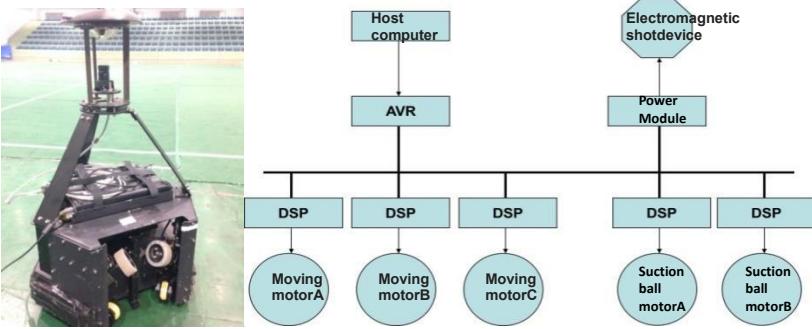
Our team has 6 robots participating the soccer match, each one is comprised of 4 parts, including the visual system, the decision-making system (i.e. the airborne laptop), the motion-control system and the communication system. The robots used in the 2014 China Open and its electrical system are shown in Fig.1 &Fig.2 respectively. The specification of our robot is 50cm in length and width, 78cm in height, with a total weight of 38kg.Our team is currently upgrading the robots, although the new players may be slightly different from that in display, we adopt the same mechanism
Motion-control system
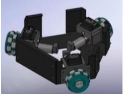
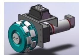
Our robots are equipped with three-wheel omni-directional system (shown in Fig.3). Each wheel is an independent unit with a high-precision 160w DC electric motor and a pro-Motion BDMC3606SH Servo Driver (shown in Fig.4). Three units together make the equilateral triangle chassis of the robot each in an angle of 120 degree with the others, which makes our robots move with dexterity in all directions, and can perform stunts like swerving, making sharp turns and encircling the target. The system is simple and easy for updates.
The mechanism for dribbling the ball
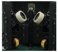
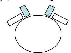
Our robot has the active device to dribble the ball, with the help of the friction between the ball and the wheels, the two 220V DC motors drive the wheels to move the ball. We can adjust the position of the wheels to control the robots to move the ball along its trajectory.
Shooting mechanism
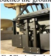
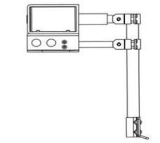
We build the electromagnetic launcher into the robot (shown in Fig.7&Fig.8), in comparison with the traditional mechanical devices and the air pumps, it saves time for battery charge and it is easy for maintenance. The levers converts the electrical energy quickly to mechanical energy. The launcher can easily adjust the shooting angels according to the conditions on the field. Our robots can perform push shot or flip shot in required velocity and angels. The robot can send the ball flying for more than 8 meters before the ball touches the ground.
Panoramic camera
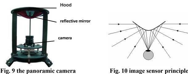
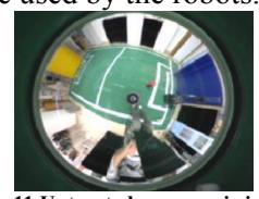
Each robot carries a camera with 640*480 pixelpixel picture, 60fps, color dynamic range wider than 90dB, as shown inFig.9 &Fig.10. The panoramic vision is the result of the conical reflector on the top of the robot, which collects the images of the surrounding objects and converge them in the camera. The advantage is that one single picture captures 360-degree image within a certain range, however, the images may need rectification algorithm as the objects further afield may be distorted.
Software Description
(Introductory section for software system description)
Panoramic image processing
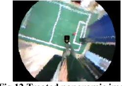
The images captured by the panoramic image camera on the robots can not be used directly for either self-positioning or allocated decisions. The overall information needs to be processed first (shown in Fig.11&Fig.12)andthen get processed information, which include the information about self-position,the position of the ball and obstacle. Those information will be used by the robots.
Color Calibration
The robots identify the objectives on the field by calibrating the colors, the color is the primary characteristics of each target. The visual identification system describes the color through three-color components (red, green, blue). However, the changes of light intensity caused great errors with the measurements even if the color components are constant, which may go against the division of the color threshold. Therefore, we convert the tree color components into HIS to search and divide different color areas, which is more widely adopted. HIS describes a color with HUE, saturation and intensity, there is also an independent HUE component and intensity component in HIS space, which is better for color discrimination.
The robots mark the field 'green', the white field lines 'light blue', the yellow football 'red', and the black robots 'purple'.
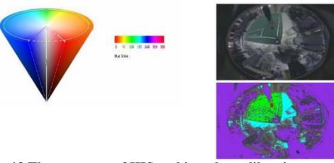
Image processing
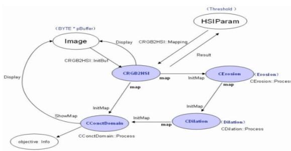
The frequency and the curve of pixel distribution are used to determine the color of the objects. The computers get the results in binary and process the images. The image processing procedure is shown in Fig.14.
Self-positioning
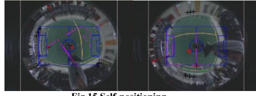
To get the overall information of the field, the self-localization of autonomous soccer robot is one of sticking points that must be solved. After distortion rectified the images, robots will analyze the images. The determination of relative position of the field tag line is done by matching the field line with a prepared field line template. The field line template is shown in blue on the screen, while the captured white lines are marked as purple and red dots. Two images did not overlap on the left figure, matching program will rotate the purple dot continually, until its main part is roughly coincide with the blue template. And, through the rotational angle and translational distance of the dot, the robots can back step its absolute coordinates in the field
Overall introduction of software
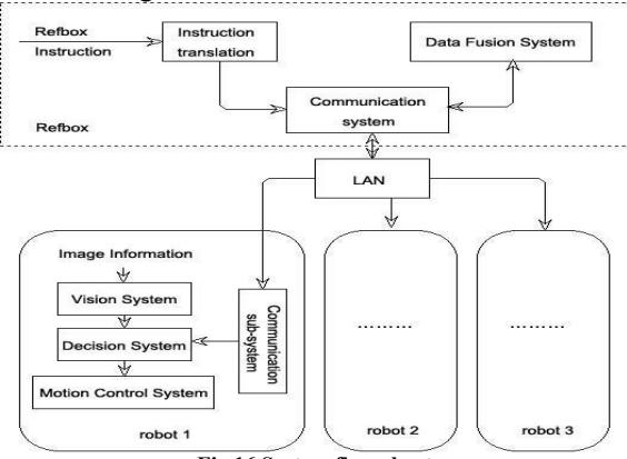
The program is divided into three parts, including the communication subsystem, decision subsystem and motion control subsystem. The flow chart of the system is shown in Fig.16.
communication subsystem
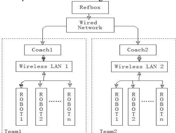
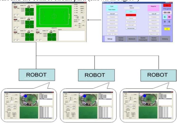
Our robots connect with each other with wireless communication. The communication subsystem consists of the computer resources, wireless routers, and the laptop wireless card in each robot. The communication subsystem controls the mobile robots to send the monitoring data and the recognition results to the coaching computer within each cycle. The coaching computer releases the information of the field and gives orders to the robots on the field. The communication process is shown in Fig.17.
Decision subsystem
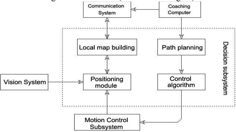
Each robot has its own decision-making system and it is implemented by the decision-making process run by the computer. Based on the obtained data and pre-set control strategies, the system decides the trajectory of the robot. The lower computer of the system is a thinkpad laptop, it communicates with 1394 camera by port 1394 and connects with the motor controller by USB data cable to exchange the information.
Motion Control Subsystem
The independent motion unit in the bottom of the robot is the motion actuator. The motion control subsystem used in each robot consists of the mechanical part and the control circuit part. The flow chart in Fig.20 outlines the overall program process.
Other Declaration
- a. During the competition, the team can carry out tasks by using the Referee Box.
- b. The team invites professionals to study the rules to guarantee correct decisions of the referees.
- c. The team meets the requirements of the wireless network communications on bandwidth usage
- d. Our team does not cooperate with any other teams as a joint team.
- e. Our team prepared six robots for the competition.