FALCONS
Christiaan Bakker, Jelm Franse, Michel Koenen, Roel Merry, Jeroen Sluijter, Stan Mertens, Jan van Mastbergen, Mathijs Brands, Cees van der Leeuw, Lex Coenen, Raf van Son, Sainath Kadam, Krzysztof Labinowicz, Lukasz Sosniak, Albert Mollema, Bogathi Reddy, Dirk-Jan Vethaak, Naveed Abbasi, Pawel Safinowski, Prabhu Mani, Prashanth Subramanya, Sundar Ravi Kumar Sankaran, Thomas Kerkhof, Ivo Matthijssen, Jaap Vos, Jan Feitsma, Tim Kouters, Mike Hoogstraten, Ruben Poorters, Andre Pool, Gerardo Santiago Flores, Umut Uyumaz, Eildert Slim, Anita van de Wetering, Rene Geltink, Ronald van der Weide, Simon van den Boom, Jan van Geenhuizen, Arjan Elands, Everhard Bos, Lutfiye Atay, Douwe Groenevelt, Roxana Tipa, Evangelos Iliadis
ASML
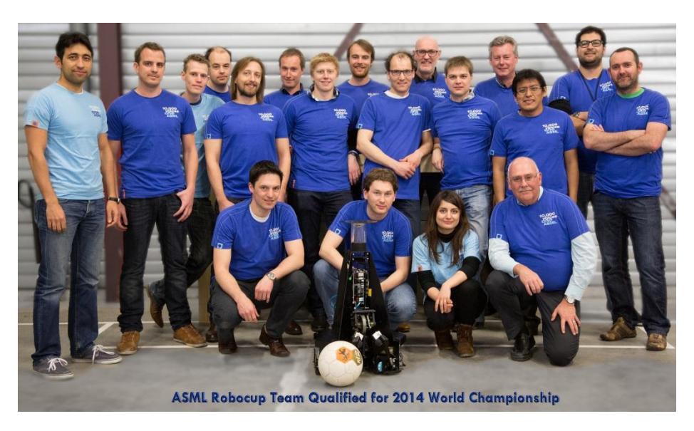
Abstract The FALCONS is the MSL RoboCup team based in Veldhoven, the Netherlands and consists of ASML employees who share the same passion and vision; develop and work with robots and become champions at RoboCup MSL in the coming years. The FALCONS team was formed in November 2013, encouraged and supported by ASML, and today counts more than 30 members. The team is structured and operates using a similar organizational structure as in ASML (system design approach, projects structure, engineers with specific tasks and competences, etc.).
Introduction
The FALCONS is the MSL RoboCup team based in Veldhoven, the Netherlands and consists of ASML employees who share the same passion and vision; develop and work with robots and become champions at RoboCup MSL in the coming years. The FALCONS team was formed in November 2013, encouraged and supported by ASML, and today counts more than 30 members. The team is structured and operates using a similar organizational structure as in ASML (system design approach, projects structure, engineers with specific tasks and competences, etc.).
Facilities and Infastructure
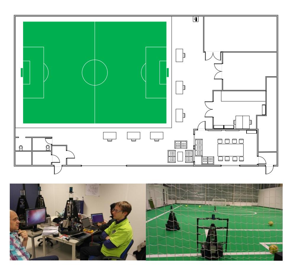
The FALCONS team shares a building with the VDL Robot Sports team in Veldhoven, the Netherlands. The building is equipped with a full size MSL soccer field (protected area with net), WiFi, meeting room and work areas. The venue has been and will be in the future also used for hosting RoboCup Workshops and local events. An overview of the described structure can be seen below.
Robot Design Roadmap
The MSL robots are based on the Turtle 5K design.
The FALCONS team has defined a technical roadmap pursuant to which the functionality of the existing robots is gradually and constantly improved and upgraded. The software design has been constantly developed for over a year, as it had to is built almost from scratch (less than 5% from original Turtle 5K exists). These improvements will also be shared with the Turtle 5K initiative, thus making them available to the whole MSL community.
Over time the robots will become more efficient on the usage of power and CPU resources, faster, safer and smarter. That roadmap, in addition to the yearly evolving MSL rules, will lead to the realization of the FALCONS' ultimate RoboCup-goal; becoming world champion at RoboCup's MSL!
Current Electrical Design
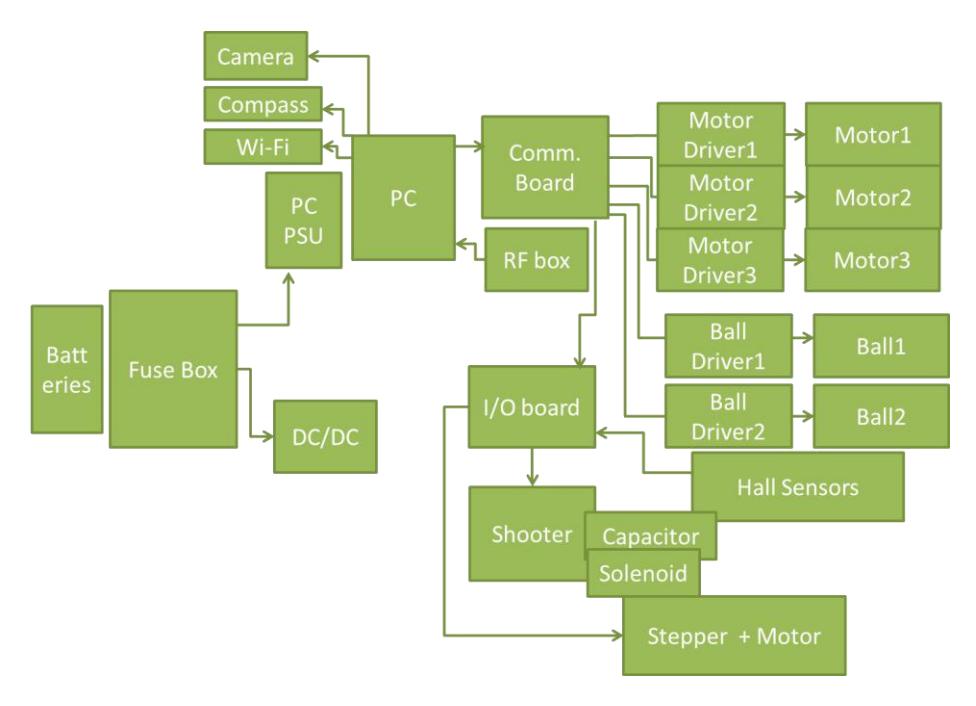
The electrical design has been improved and made safer compared to the original Turtle 5K design although the main architecture remains the same.
The wiring was considered to be under dimensioned and the grounding concept was wrong. The High Voltage shooter electronics was completely re-developed in house to make it safer with better performance and efficiency. The robot is powered by 2 batteries of 24V, connected in parallel, which supply the whole robot. Before they reach the electrical parts and peripherals, the voltages are regulated and protected with fuses while the whole robot can be disabled/enabled wirelessly or on the spot via an emergency switch. The emergency circuitry was redesigned such that the PC stays on after an "remote switch off command" This enables faster rebooting time. The internal power supply of the PC box was under dimensioned and replaced by a more powerful version. The onboard PC runs the needed software while all actuators (motors, solenoid and sensors) are reached via peripheral control boards. The in-between communication is done using RS422 communication protocol.
Current Mechanical Design
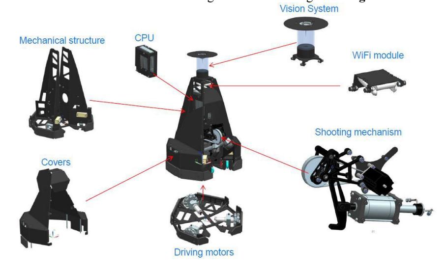
The mechanical design has so far not changed much from the original Turtle 5K. The dimensions are 52cm x 52cm and height 80cm. The weight is 38kg.
The supporting frame of the robot consists of 6mm thick steel. Sheet metal parts are used to reduce costs and milling time. The covers of the robot are made of 3mm aluminum sheets. The Turtle 5k uses 3 separate motors that drive 3 omni-wheels which allow the robot to move freely in any direction.
The ball handling mechanism consists of 2 rotating aluminum arms; each of them has one actively driven wheel. They are driven by 2 Maxon motors via a gearbox. Two springs make sure the active wheels keep in touch with the ball.
The ball handling motor speed is proportional with the angle of the ball handling arms. The angle is measured and fed back into the control loop. Working principle:
- The robot moves towards the ball while the active wheels are spinning.
- The ball makes contact with at least 1 active wheel.
- The active wheel spins the ball in such a way that the ball moves to the center of the robot and makes contact with the second active wheel.
- Now the ball gets pulled inside the Turtle 5k until it touches the passive wheels.
- While the robot is moving, the active wheels spin the ball in such a way so that it follows the robots movement.
The shooting mechanism is powered by a solenoid. It pushes a kicker with a high force speed against the ball. The kicker is adjustable, by software, in height to enable of shooting of lob or straight shots. This is done by a stepper motor which drives the arm to lift the kicker.
The team is working on improvements on the shooting mechanism, the signal reception, the ball handling mechanism and other items. The possibility to drive with more or less than three wheels is also under investigation.
Current Software Design
The software is built using Robot Operating System (ROS), the OpenCV framework and Python scripts; all widely used open-source frameworks. This resulted in a complete redesign of the software.
ROS mainly consists of nodes that carry out tasks associated with them, with or without relying on the input of other nodes. Related nodes are generally grouped in packages. The nodes subscribe or publish to Topics that carry data from one node to another. Topics are the 'lines' that connect all the nodes together. All of these nodes and Topics are registered with a central software service called the ROS-core.
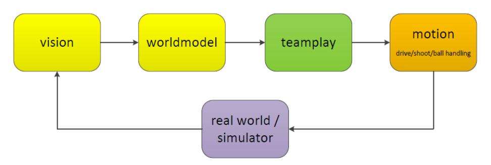
The messaging mechanism ROS uses for the communication between nodes is not very suitable for Real-Time controls or large data transfers. The parts require much faster processing are written as firmware on the embedded motion boards. Higher level software modules that generally do not require Real-Time processing are designed in ROS, communication between ROS and the firmware is done via a middleware library written in Python. This allows the time-critical low level control loops, e.g. velocity-controlled driving and the ball handling feedback mechanism, to run at a higher frequency. The software data flow is represented in the figure below.
Each peripheral has a microcontroller and firmware. ROS access each firmware via the Middleware. Both ROS and Middleware run on Linux environment. The Middleware (also known as the API or Drivers) is a software layer in between the ROS software and the Firmware. It uses Pyro4 (Remote Object Communication) to communicate with the ROS and uses serial ports to communicate with the hardware peripherals (firmware).
The software architecture can roughly be divided into Vision, World Model, Team Play and Motion.
The Vision package of the software comprises of two main nodes that perform ball/obstacle detection and localization. The Vision package communicates with the Robot to receive input from the camera and compass. With the information gathered from Vision and Motion the World Model is created.
Team Play uses information from the World Model to determine an action plan. This action plan is communicated to nodes that define Motion: path planning, driving, shooting and ball handling. Together these nodes perform the predefined action plan.
PathPlanning steers the robot to any given target position using the Potential Field Method (PFM). This is achieved in a direct way, rather than performing actual trajectory planning. At each instance in time (20Hz), the algorithm generates a speed setpoint.
Team Play is the software development and architecture which aims to develop software that can make strategic decisions based on current robot status and gameplay situation. Decisions can be made on either coach level (teamplay_coach) or on individual robot level (teamplay_robot).
Movement, Shooting and Driving belong to the Motion part.
Shooting controls the shooting mechanism, which makes use of a shooting lever and an actuator. The height of the point where the shooting lever makes contact with the ball can be adjusted with a stepper motor and the force applied by the solenoid actuator can also be controlled.
The shooting algorithm is implemented in a ROS package, while the control of the hardware (stepper motor and actuator) is implemented in firmware and a middleware library as described above. The ROS package receives inputs from the World Model and Team Play to determine the shooting target in three dimensions. It calculates the angle of the shooting lever, velocity of the actuator and orientation error. First it transforms the absolute shot target into a relative target, then commands Path Planning to make orientation adjustments if needed. Next in controls the height-adjustment mechanism and finally gives the command to the firmware to shoot with a certain power. The ball handling mechanism is used to catch the ball and keep it close to the robot while moving. This mechanism consists of two ball handling arms (each with a driven wheel) and two passive omni-wheels to keep the ball from entering the robot too far. The ball handling arms can freely move and their position is used in the ball handling calculations. The software is implemented both in ROS and Firmware. The software consists of a velocity and angle feedback loop in combination with a feed forward controller. The module in ROS reads the current velocity of the robot in x, y and theta, and sends a feed-forward reference to the firmware. The embedded logic supplements this with the feedback and ball handling-arm angle error and performs compensations based on measured errors and preset gains. The module then computes the desired speed for the two ball handling motors and controls the motor controllers for ball handling.
The Driving package receives the desired velocity for the robot in x, y and theta from the Path Planning ROS package. Encoder signals from the omni-wheels are read and used for local velocity control on the embedded boards. This minimizes communication on the serials ports of the computer and thereby negates the risk of buffer overflow or lost packages.
Integration Process
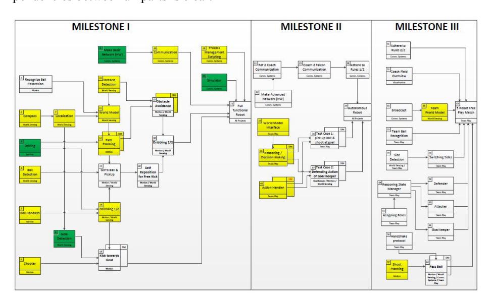
Since all of the software and hardware need to be tested for the very first time an integration plan was made to test and validate everything step by step. All steps are small functions of the robot (like 'shooter', 'driving', 'ball handlers', 'listen to ref box', etc.) and contain all deliveries (hardware, software, firmware, tuning parameters, …)
for that part of the robot. By finishing a part it is sure that that part is fully tested and really working.
In the schematic below the logical sequence between all steps is shown. The finishing of each step is depending on the successful finishing of the previous step(s). This way working in parallel on multiple deliverables is still possible, but the priority and dependencies between all parts is clear.
3 mayor milestones are defined which indicate the high level status of the robot integration. The first milestone (full functional robot) indicates that the robot is physically able to perform all tasks when the correct SW trigger is given.
Reaching the second milestone (Autonomous Robot) indicates that the robot is able to perform (some) tasks autonomous. This milestone is important because it shows that the basic reasoning functions are working and that the robot is able to listen to the ref box communication.
Finally the third milestone indicates that the team of robots is ready for playing a match meaning that not only one robot is working fully autonomously, but also all team communication being integrated.
MSL Workshop and Future Activities
The FALCONS successfully participated in the MSL workshop on 'Data Model Standardization for Inter-Robot Communication in RoboCup MSL', and supported it by hosting it in Veldhoven, the Netherlands.
The team plans to participate as many events as possible for gaining experience but also organize local events which will be used for strategy and hardware improvement.