Tech United Eindhoven Team Description 2015
Cesar Lopez, Ferry Schoenmakers, Koen Meessen, Yanick Douven, Harrie van de Loo, Dennis Bruijnen, Wouter Aangenent, Bob van Ninhuijs, Matthias Briegel, Patrick van Brakel, Frank Botden, Robin Soetens, Tom Albers, Jan Romme, Stefan Heijmans, Camiel Beeren, Marjon van 't Klooster, Remco Oudshoorn, Lotte de Koning, René van de Molengraft
Eindhoven University of Technology, Den Dolech 2, P.O. Box 513, 5600 MB Eindhoven, The Netherlands
www.techunited.nl · http://www.roboticopenplatform.org/wiki/TURTLE · http://techunited.nl/en/turtle-qualification
Abstract In this paper we discuss the progress in mechanical, electrical and software design of our middle-size league robots over the past year. Recent process in software includes intercepting a lob pass and get a 3D image by using combined omnivision of different robots. To improve the acceleration capabilities of the three-wheeled robot an a-symmetric trajectory planner is developed and implemented. For better localization the distance mapping and mapping center are determined during the game to compensate for tilt variations. Human-robot interaction is this year implemented by using hand gestures to pass coaching instructions to our robots. Finally a simulator link is developed to run a simulation with multiple computers, therefore, more robots could be included in the simulation, which makes it possible to simulate matches of two teams competing against each other.
1 Introduction
Tech United Eindhoven is a RoboCup team of Eindhoven University of Technology. Our teams consists of PhD, MSc and BSc students, supplemented with academic staff members from different departments. The team was founded in 2005, originally only participating in the Middle-Size League (MSL). Six years later service robot AMIGO was added to the team, which participates in the RoboCup@Home league. Knowledge acquired in designing our soccer robots proved to be an important resource in creating a service robot.
This paper describes our major scientific improvements over the past year. It is a part of the qualification package for the RoboCup 2015 World Championships in China and contains five main sections. First we introduce our current robot platform followed by the robot skills we have improved. Here we will mainly focuss on the improved ball position estimation, intercepting lob passes and a improved trajectory planner. Hereafter we describe the the improved localization followed by new human-robot interaction. Finally a simulator link is introduced, which makes it possible to run one simulation using multiple computers.
2 Robot Platform
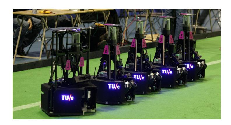
Our robots have been named TURTLEs (acronym for Tech United RoboCup Team: Limited Edition). Currently we are employing the fifth redesign of these robots, built in 2009, together with a goalkeeper robot which was built one year later (Fig. 1). Development of these robots started in 2005. During tournaments and demonstrations, this generation of soccer robots has proven to be very robust. The schematic representation published in an earlier team description paper [3] still cover the main outline of our robot design.
Changes regarding the robot platform, the 12V Maxon motors will this year be driven by Elmec Violin 15/60 amplifiers and two Lithium Polymer batteries. A detailed list of hardware specifications, along with CAD files of the base, upper-body, ball handling and shooting mechanism, has been published on a ROP wiki. And our qualification page contains a detailed overview of the mechanical and electrical hardware design and the software architecture.
3 Ball perception
Last year a kinect sensor is added to all robots to observe balls which are moving higher through the air. But there are some limitations with the kinect sensor. The kinect sensor is only added on the frontside of the robot with sight in only one direction and secondly, the ball estimation measurements are inaccurate when using both the kinect en omnivision sensor if the ball comes of the ground, because the the ball model is immediately disturbed by the omnivision data. Therefore a method is introduced to estimate ball positions for balls which are close to the ground using combined omnivision from different robots.
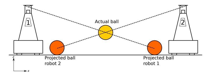
The current omnivision algorithm projects the observed ball on the field to obtain its x and y coordinate. This results in an offset if the ball is moving through the air. A possible solution to estimate this offset and to include the z coordinate of the ball s to use triangulation. To triangulate the 3D position of the ball, at least two robots with vision on the ball are needed. The vision lines of the robots and their projected balls are known (Figure 2). If we know at least two vision lines, an intersect point of all lines can be calculated. The actual ball should be on the intersection point of those lines. And therefore, the actual ball position on a 3D axis is calculated.
3.0.1 Ball model
A ball model is required to extract relevant information from the ball position measurements. A hypothesis-tree based sequential clustering algorithm [4] is adopted, with some adaptations to make it run in real-time and to deal with the ball dynamics. An estimate of the current ball state is returned. Figure 3 shows a x, z plot of the ball estimate for a simulated lob pass with noise on the ball measurements.
![Fig. 3. Ball state estimate for a simulated lob pass with noise. x is measured ball position, [ˆx, v] is estimated ball state.](/tdps/soccer_midsize__2015__TechUnited/_page_2_Figure_3.jpeg)
3.0.2 Intercept strategy
The receiving robot corrects for the shooting inaccuracy using a set of predictions for the bounce locations. The most favourable interception point is the current ball-tracking based prediction, derived from measured ball positions during the lob pass. The least favourable interception point is the initial estimate, as derived by the pass-giver before shooting.
Figure 4 shows a flowchart-diagram of the intercept strategy. First, several validation conditions are evaluated. One of these conditions is an accuracy constraint. Due to noise on the ball measurements, the ball-tracking based predictions can be modelled as a bivariate distribution. The accuracy is derived from the sample covariance on a buffer of prediction locations. For all valid predictions, a intercept confidence rating is determined, based on the estimated time of arrival and the magnitude and velocity of the incoming ball vector at intercept.

4 A-symmetric trajectory planner
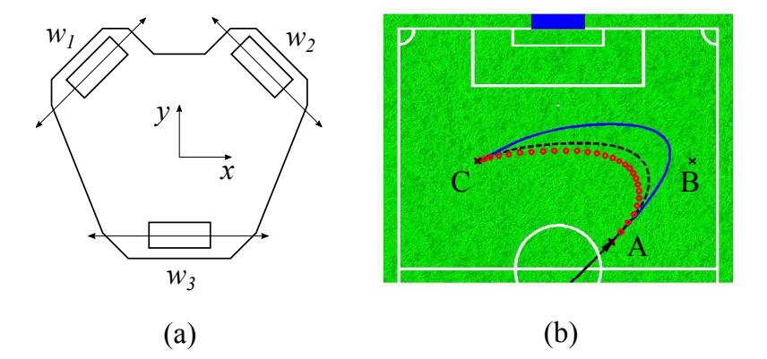
One of the major drawbacks of the three-wheeled robot of Tech United is its orientation dependent acceleration capability. This is caused by the angle between the wheels illustrated in Figure 5a. When the robot drives forwards or backwards, i.e. in the y-direction, wheel one (w1) and two (w2) are active while wheel three (w3) does not provide torque/force. If the robot drives in the x-direction or rotates, all three wheels are active and providing torque/force.
During a RoboCup game, the robot is mainly driving in the positive y-direction towards or with the ball. During defensive actions or positioning to receive a pass, the robot will also driving in the x-direction. When the robot accelerates in the forward (positive y-) direction, the normal force of the front-wheels is reduced due to backwards tilt of the robot. In case that the robot decelerates, when driving in the positive y-direction, the normal force on the front-wheels is increased caused by the inverse tilt. The friction force between the wheels and the ground is proportional to the normal force of the robot to the ground surface. This friction between the wheels and robot determines the maximum acceleration of the robot without having slip. Hence, the maximum acceleration value is theoretically lower than the maximum deceleration value when driving forwards.
Ideally, the trajectory planner should take into account the wheel configuration, the center of gravity and the grip of the omni-wheels to minimize the slip and maximize the acceleration and deceleration. An a-symmetric trajectory planner is proposed as a first step towards a more effective trajectory-planner. This trajectory-planner uses different limits for the acceleration and the deceleration phase of a trajectory. The resulting trajectories are faster because the robot will drive for a longer time at its maximum speed and the robot will be more agile because it can decelerate faster when its target changes while driving.
The trajectory-planner is implemented as a 2-DoF planner for x, y and a 1-DoF planner for φ. This means that the acceleration limit is treated as a 2-DoF constraint for x and y, i.e., a $2x + a 2y ≤ a 2 max$. An optional flag can be used to reduce the acceleration of φ such that the duration of the φ-trajectory is equal to the xy-trajectory. This reduces the slip probability in the situation that the trajectory duration in xy is longer than the trajectory duration in φ. The output of the planner is a second order position profile (discontinuous acceleration) which is used as a position setpoint for the position controller of the robot.
Figure 5b illustrates an example of the effect of the a-symmetry in the trajectory. The robot is moving towards position B at full speed (3 ms$^{−1}$) and decides at position A to change its target from position B to position C. The solid line illustrates the fastest trajectory to C if the maximum acceleration and deceleration are equal (1.5 ms$^{−2}$). The black dashed line (- - -) is the resulting trajectory if the deceleration is set to 150% of the acceleration. The red dotted line (-·-·-) is the result of a deceleration set to 200% of the acceleration. It can be seen that the resulting trajectory is much faster. The deceleration to acceleration ratio will be tuned and tested in several situations to make the robot more agile during the game.
5 Adaptation of localization parameters
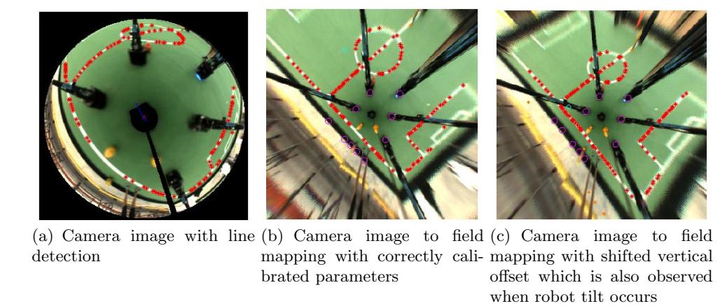
For localization, line points in the camera image are being mapped onto an a priori known field geometry. The left image in Figure 6 shows such a camera image. As explained in [1], this line points mapping is parameterized with 9 parameters:
- Distance mapping from pixels to meters (2 parameters)
- Mapping center (2 parameters)
- Robot center (2 parameters)
- Robot pose (x,y,ϕ) (3 parameters)
These parameters are calibrated offline with a number of images at different locations using global optimization. By separating the mapping center and the robot center, small tilts of the camera and/or mirror can be compensated for. If the mapping parameters are calibrated well, a mapped image is obtained as shown in the middle image of Figure 6. If the parameters are not calibrated well, the right image is obtained. A similar distortion is obtained when the robot is tilted, hence, this provides a possibility to compensate for tilts.
6 Human coaching
For the previous RoboCup MSL, the human-robot coaching was introduced, making it possible to instruct a robot with high-level instructions like 'shoot more often' or to change tactics, for example how to take a free kick.
To stimulate innovation, coaching by means of qr-codes is no longer permitted at this years RoboCup. As a result, new ways of communication with the robots is needed, leading to the introduction of hand gesture recognition by using the kinect cameras. At first, the principle behind this technique is based on a dedicated geometric descriptor, where a convex hull and its convexity defects are used to detect the shape of the hand [2]. Using the openCV library one can easily extract this information out of the incoming images.
While this concept has been proven to work almost flawless, some difficulties have been encountered during the implementation and experimentation of it, especially with the recognition rate in different lighting conditions. As a result, a more robust concept will be developed, based on the seven Hu invariant moments on a binary image of the hand [5]. In order to achieve this, the incoming images first need to be filtered and converted to a binary image, to ensure a faster and more accurate detection of the hands. Hereto, two major steps are performed, i.e. the filtering based on color and on depth. Filtering on depth implies losing all the pixels (set them to black or 0 in the binary image) that are too far away (over 5 meters) or too close by (less than 50 cm). The filtering on color implies that every pixel that has a color within a predefined range is set to 1 in the binary image, while all other pixels are set to 0. When done correctly, a binary image showing only the wanted hand to recognize will be the result. However, a well known problem with hand gesture recognition is the color of the hands, which is extremely difficult to detect, especially in varying lighting conditions. To solve this, a glove with a distinctive color will be used, however an alternative could be working in the Y CbCr color space.
Once this binary image has been obtained, the Hu moments can be compared to the Hu moments of known gestures stored in a database, where the values resulted from many experiments. The goal of this new approach to have at least five different hand gestures to be recognized with a 80% recognition rate, however testing should still confirm this.
7 Simulator link
The Tech United simulator enables RoboCup developers to simulate the behaviour of the Tech United soccer robots without the need to run their program on actual robots. Therefore, the development process gets expedited considerably. The simulator runs the same programs that are used on the actual robots with the exception that all modules interacting with the hardware have been replaced by modules that imitate the robots' behaviour. Furthermore, the behaviour of the ball is simulated using an advanced physical model.
By only simulating the behaviour of the low-level hardware, the simulations become highly representative of the behaviour of the robots on the field. One of the drawbacks of this approach is that it is computationally expensive, because the software of several robots, which usually runs on the separate embedded PCs of the robots, is now run on a single computer. As a consequence, the number of robots that can actually be simulated is limited.
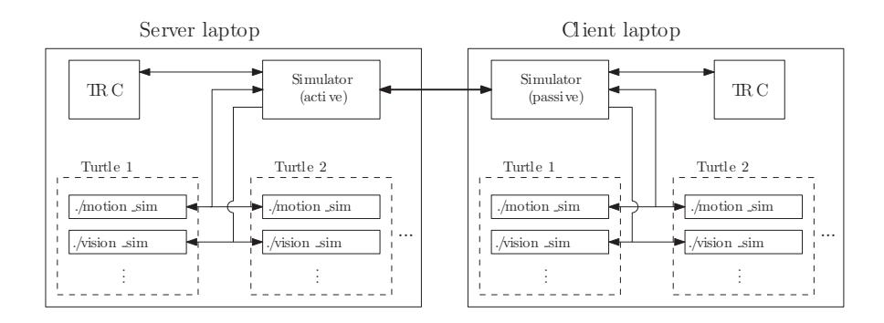
In order to increase this number, the so-called 'Simulator Link' has been developed. It is a communication interface, which makes it possible to connect two Tech United simulators that run on different computers, and thereby makes it possible to simulate matches of two teams competing against each other. Every team is simulated on a separate computer, and the 'Simulator Link' communicates the data that needs to be exchanged, like the ball and robot positions, between the computers. This is done by adding a communication module to the simulator, which handles the communication between computers and the different processes running on the same computer. An illustration of the communication architecture can be seen in Figure 7.
8 Conclusions
In our team description paper we have discussed concrete steps towards more accurate ball position estimation which, enables intercepting lob balls. Furthermore an a-symmetric trajectory planner is implemented for improved acceleration capabilities and the localization software is improved by compensating for small tilt of the camera. Finally we have developed hand gesture based humancoaching software and a simulator link allows to run one simulation using multiple computers. Altogether we hope our progress contributes to an even higher level of dynamic an scientifically challenging robot soccer during RoboCup 2015 in China. While at the same time maintaining the attractiveness of our competition for a general audience.
References
- Dennis Bruijnen, Wouter Aangenent, Jeroen van Helvoort, and René van de Molengraft. From Vision to Realtime Motion Control for the RoboCup Domain. In IEEE International Conference on Control Applications, pages 545–550, Singapore, 2007.
- Bruno Emile Jean-Francois Collumeau, Remy Leconge and Helene Laurent. Hand gesture recognition using a dedicated geometric descriptor. Image Processing Theory, Tools and Applications (IPTA),3rd International Conference on, 2012.
- Tech United Eindhoven MSL. Tech united eindhoven team description 2014, 2014.
- H.J. Schubert. Sequential clustering with particle filters - Estimating the number of clusters from data. Proc. 8th Intern. Conference on Information Fusion, 2005.
- Yanmin Yin Yun Liu and Shujun Zhang. Hand Gesture Recognition Based on HU Moments in Interaction of Virtual Reality. Intelligent Human-Machine Systems and Cybernetics (IHMSC), 4th International Conference on, 2012.