FALCONS Team Description Paper
Jaap Vos
FALCONS Team, Veldhoven, Netherlands (ASML)
Abstract This paper describes the FALCONS team, an MSL RoboCup team based in Veldhoven, the Netherlands, consisting of ASML employees. The paper outlines the team's facilities, robot design based on the Turtle 5K platform, software architecture built on ROS, and participation in RoboCup events.
Introduction
FALCONS is a team based in Veldhoven in the Netherlands and consists of ASML employees who share the same passion and vision; work with robots as a hobby and become champions at Robocup MSL in the coming years.
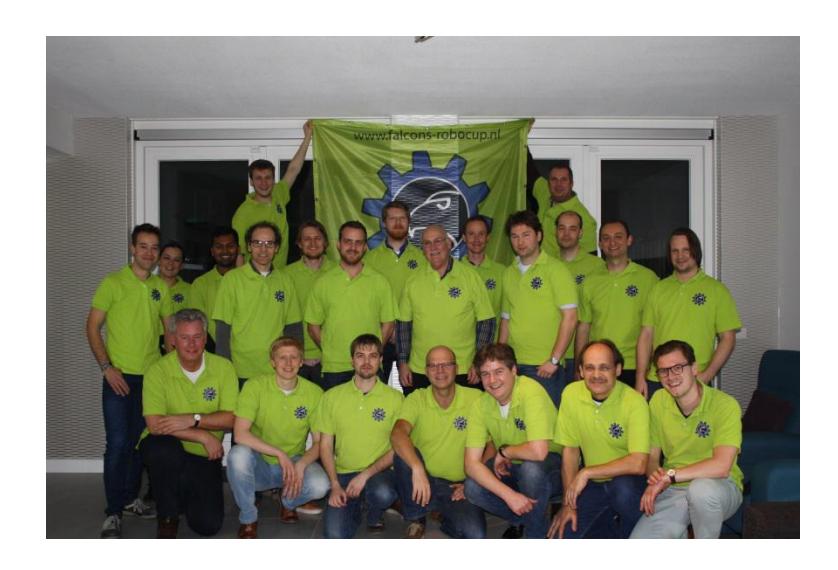
The Falcons team was formed in November 2013, encouraged and supported by ASML, and today counts more than 30 members.
The team is divided in several groups:
- Hardware
- Firmware
- Motion
- Team play
- Vision
- World Model
- Simulator and diagnostics
- Logistics
- Branding-Recruitment
- Legal
- Facilities
- Goalkeeper
- IT and infrastructure
- Project Planning
- Demo team
Facilities and Infrastructure
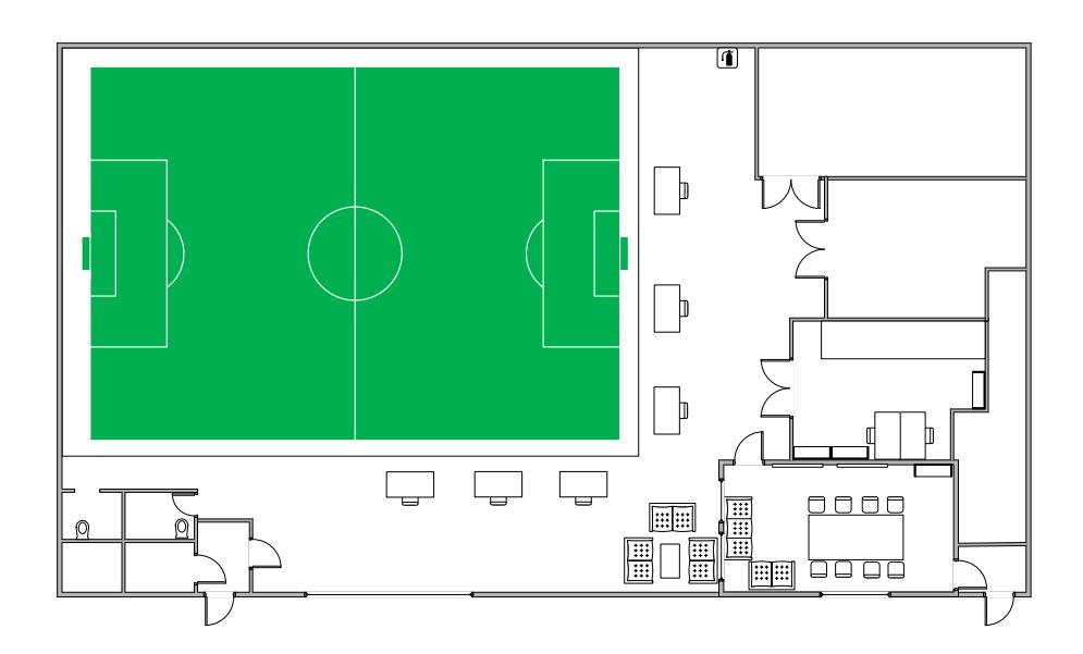
The FALCONS team shares a building with VDL Robot Sports team in Veldhoven, the Netherlands. The building is equipped with a full size 18x12 m MSL soccer field (protected area with a net), Wi-Fi, meeting room and work areas which can be used for hosting Robocup Workshops and local events. (Including work space and tools for repairs).
Robot Design Roadmap
The MSL robots from the Falcons team are based on the Turtle 5K design.
The FALCONS team has defined a technical roadmap which will constantly enrich the functionality of the existing robots. Eventually the robots will be more efficient on the usage of power and CPU resources. Furthermore we are working on getting the robots faster, safer and smarter.
That roadmap in addition to the yearly evolving MSL rules will lead to the ultimate Robocup goal; becoming world champion!
Current Design
The current robot hardware (mechanics & electronics) design of the FALCONS team is based on the Turtle 5K design with many changes. The software design is built from scratch and it is been worked on for over two years. Currently we are emphasizing on stability and responsiveness.
Normal Turtle 5K Design
The electrical design has been improved and made safer compared to the original Turtle 5K design but the main architecture remains the same.
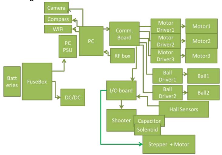
There are 2 batteries of 24V, connected in parallel, which supply the whole robot. Before they reach the electrical parts and peripherals, the voltages are regulated and protected with fuses while the whole robot can be disabled / enabled by a wireless RF switch or on the spot via an emergency switch. The onboard PC runs the needed software while all actuators (motors, solenoid and sensors) are reached via peripheral control boards. The internal communication was done with RS422 communication protocol, but has changed to USB in 2016. The Comm. board in the drawing below has been changed to a USB hub and communication electronics on the motor driver and ball handling boards has been altered to accommodate this USB design.
Current Mechanical Design
The mechanical design is not much changed from the original Turtle 5K design, but it will be in the coming years.
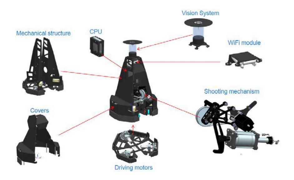
The supporting frame of the robot consists of a 6mm thick steel baseplate on which an aluminum frame is bolted. Sheet metal parts are used to reduce costs and milling time.
The covers of the robot are made of 3mm aluminum sheets.
The Turtle 5K uses 3 separate motors with gear boxes that drive 3 omni-wheels which allow the robot to move freely in any direction.
The ball handling mechanism consists of 2 rotating aluminum arms; each of them has one actively driven wheel. They are driven by 2 Maxon motors via a gearbox. Two springs will make sure the wheels keep in touch with the ball.
Working principle:
- The Turtle 5K moves towards the ball while the active wheels are spinning.
- The Ball makes contact with at least 1 active wheel.
- The wheel spins the ball in such a way that moves to the center of the robot and makes contact with the 2nd wheel.
- Now the ball gets pulled inside the Turtle 5K until it touches the passive wheels.
- While the robot is moving, the active wheels spin the ball in a certain way so it follows the robots movement.
The shooting mechanism is powered by a solenoid and a High Voltage driver. It pushes a kicker with a high force against the ball. The High Voltage and therefore the kicker force are adjustable via software. The kicker is adjustable in height to shoot lob shots. This is done by a stepper motor which drives the arm to lift the kicker.
Electrical design changes in 2016
- The internal communication was done using the RS422 communication protocol, but has changed to USB in 2016. The Communication board in the drawing above has been changed to a USB hub and communication electronics on the motor driver and ball handling boards has been internally altered to accommodate this USB design. Also the firmware was totally re-written for the re-design to incorporate a robust protocol that can cope with packet loss.
- The HV shooter box has been modified for a much safer design while at the same time the reload time is shorter and efficiency is about 50% better.
- The WIFI antenna is changed for better reception
- The I/O board has been changed into a Beagle Bone Black, with a dedicated extra board on top.
- The compass has been changed into a compass/gyro assy with more rugged mounting.
- Internal wiring was changed to allow for expected currents.
- A proper grounding concept was implemented.
Mechanical design changes for 2016
• The ball handling arm are mechanically changed to allow for a bigger "catch angle"
Current Software Design
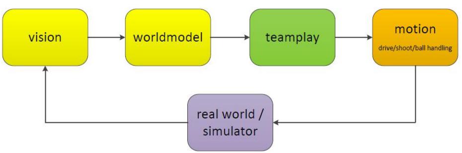
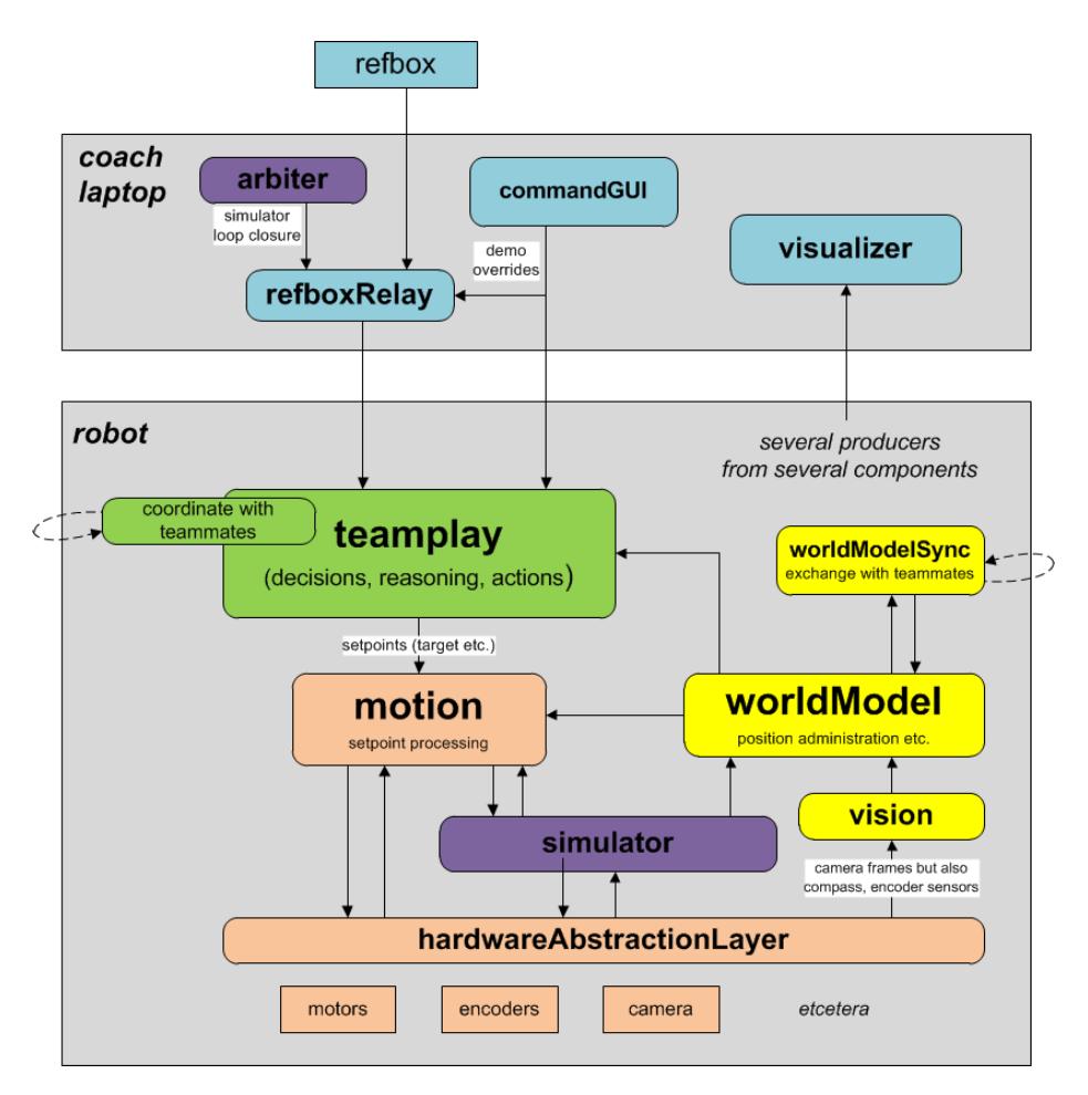
The software is built on Robot Operating System (ROS) software and runs on Linux. The software data flow is represented in the figure below.
The software architecture can roughly be divided into Vision, World Model, Team Play and Motion. The Vision package of the software comprises of two main nodes that perform ball/obstacle detection and localization.
The Vision package communicates with the Robot to receive input from the camera and compass. With the information gathered from Vision and Motion the World Model is created.
Team Play uses information from the World Model to determine an action plan. This action plan is communicated to nodes that define Motion: path planning, driving, shooting and ball handling. Together these nodes perform the predefined action plan.
Team Play is the software development and architecture which aims to develop software that can make strategic decisions based on current robot status and gameplay situation. Decisions can be made on either coach level (teamplay_coach) or on individual robot level (teamplay_robot). Motion deals with the driving, shooting and ball handling of the robot.
Each peripheral has a microcontroller and its firmware. ROS accesses each Firmware via the peripheral interface. Both ROS and peripheral interface run in Linux environment. The peripheral interface (also known as the API or Drivers) is a software layer in between the ROS software and the Firmware. It uses an own protocol to communicate with the ROS and uses USB ports to communicate with the hardware peripherals (firmware).
Software improvements
The last two year we heavily depended on creation of new functionality. This year we emphasize more on stability and responsiveness. For stability we are creating autotesters for our code. For these autotesters, robotframework and google test is used. When new code is committed, the build server will run the tests automatically and inform when errors occurred.
To enable parallel work in software creation, we migrated from subversion to GIT. During the migration, old code is removed by actively refactoring and the file structure is changed to enhance consistency and readability of the code.
Teamplay defined a new architecture that is scalable for future use. This architecture is currently being implemented as part of the proactive refactoring in code. The new design is set up in a modular fashion and separates internal data-types from the ROS-environment.
For responsiveness of our software, we defined an event-based design instead of having a loop running per task. Teamplay will orchestrate the action a robot will perform which will be event-based completely downwards in the architecture.
Team's performance on past Events
Although the team is quite new, it successfully participated and supported the RoboCup community.
The team participated in:
- MSL International workshop 2015 Aveiro, Portugal
- Robocup World Championship 2015 Hefei, China
- Portuguese Robotics open 2015 Villa Real, Portugal
- MSL International workshop 2014 Eindhoven, The Netherlands