MRL Middle Size Team: Robocup 2017 Team Description Paper
H.RasamFard, H.Haeri, A.H.MaaroofMashat, E.Marjani, M.AmirSardari
Mechatronics Research Laboratory, Islamic Azad University of Qazvin - IRAN
Abstract The paper mainly describes the implementation of our middle-size league robot team "MRL" for Robocup 2017 with the improvements made since the previous years. Our major concerns for this year's competitions have been developing a new high level control system, designing a new robot structure, designing a new ball handling system, also designing a new kicking system.
1 Introduction
The MRL middle size team has started its work at Mechatronic Research Laboratory of Azad University of Qazvin since Aug 2003. This team aims at establishing an intelligent control method for autonomous multi-robot systems in dynamic uncertain environment. MRL has begun the research and work in MSL since 2004. Our first official participation was during Robocup 2005 competitions in Osaka and then Robocup 2006 in Bremen. We optimized hardware, control and software system for Robocup 2008 and designed robust system for Robocup 2009 in Graz, as a result we find ourselves between four top teams. In Robocup Singapore 2010 competitions we got the first place of technical challenge and again fourth place of league competitions. Also, we got second place of free challenge and fifth place of league in Robocup Turkey 2011 competitions. After a year of hard work, we managed to get the second place of league in Robocup Mexico City 2012 competitions. Luckily another achievement of the team was getting the 1st place of technical challenge in Robocup Of China in 2015. We believe that, the Intelligent, cooperative and adaptive behavior of the robots is very important factor for a team success. With this regard our research is continuously focused on: reliability, sensor fusion, dealing with uncertainty of environment for the robots, world modeling and dealing with missing information. In the following sections we briefly explain current status and new achievements of our team.
2 Hardware and mechanic
The first participation of team MRL in RoboCup Middle Size Soccer league was in RoboCup 2005. Since that time, there were 4 generation of platforms in which some mechanisms and parts have been changed. In every design procedure, some of the previews problems have been detected and solved which is explained respectively.
2.1 Previous mechanic design
Fig. 1. MRL 4-Wheels robot. Table 1. Hardware specification of the robot
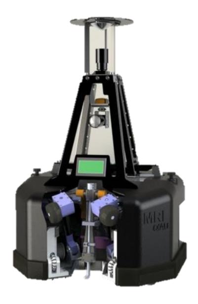
Table 1. Hardware specification of the robot
| Items | Description |
|---|---|
| Platform | 4 wheel Omnidirectional |
| Max speed | 3.5 m/s |
| Max acceleration | 4 m/s² |
| Kicker | Electromagnetic |
| Weight | 40 Kg |
| Laptop | Lenovo X200 |
| Camera | uEye UI-2210-C |
| Image processing | Omni directional mirror |
| Other sensor | IMU and IR |
| Controller | Neural Network PID |
| Spin back | Active 60watt 24V DC motor |
2.2 Mechanical problems of previous design
The old design is concerned with some of critical problems and bugs. In this section, these bugs and their destructive effects on robot's operation are discussed. The next sections focus on the new designs and given solutions.
2.2.1 Detachment of wheels from the ground
This fundamental problem is one of the main problems of the robots. Based on the observations, as the robot moves in the field, it is highly probable that it encounters with a step shape offset on the ground which is generally due to the arena's building tolerance. Since the old design has 4 wheels, these small offsets, cause an unequal distribution of the weight on the wheels so much that one wheel might completely detach from the ground. This happening would disrupt the normal kinematic behavior of the robot and results an Inappropriate and unstable path following in the field.
2.2.2 Insufficient acceleration of the robot
As the more teams join RoboCup MSL, the quality of matches rates up. Every year, the teams get smarter, more accurate and more efficient. Correspondingly, teams get faster too. Based on observations, our robots' pace in the games is relatively low and this means that the robot's acceleration is insufficient. This problem might due to one of these two things, (1) inability of actuators to provide enough torque for acceleration, or (2) insufficient friction between the wheels and the ground. So, first of all, the real problem must be detected.
Calculations shows that the acceleration provided by actuators is much greater than current acceleration of the robot. So, it can be concluded that the friction between the wheels and the ground is limiting the traction force.
2.2.3 Inaccuracy of ball kicking
The current kicker mechanism uses an electromagnetic solenoid to provide the momentum required to kick. The problem is that this mechanism cannot exactly kick the ball with desired chip angle. Moreover, the intensity of the shot cannot be controlled because of the huge variety of wasted power.
2.3.1 Locomotion Mechanisms
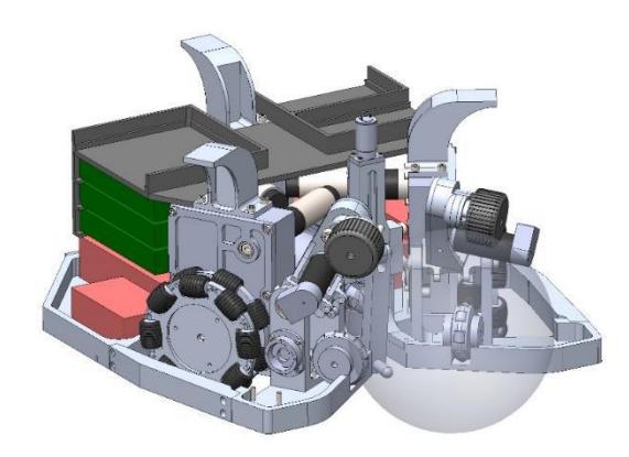
Perhaps the most fundamental change in this generation of the platform is alteration of 4-wheel based to 3-wheel based locomotion. The main reason of this alteration is to maintain all wheels' contact with the ground even the robot is moving in an uneven field.
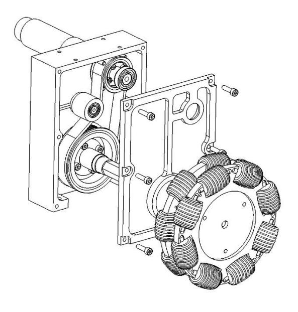
Like the previews design, in this design timing belts are used to couple the Maxon gearhead's shaft to the wheel's shaft. The reduction ratio is the same (1:2) but the thickness of the pulleys has been decreased. This decrement leads an increment for the diameter of the pulleys.
2.3.2 Kicker Mechanism
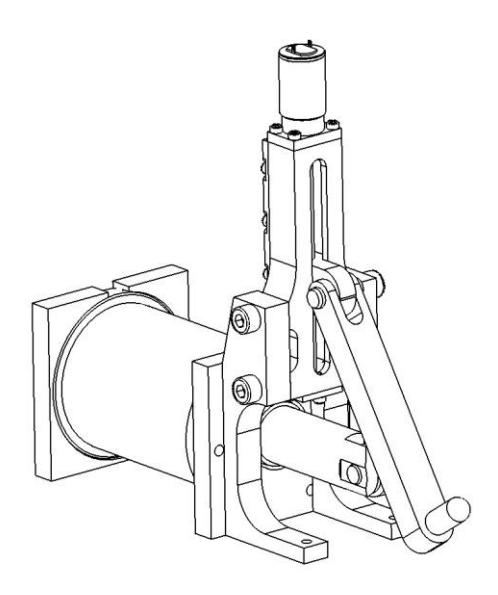
The main development of this design in this section is its capability of controlling the vertical angle of the shots. This design makes the robot able to use chip shot while attacking and also use a precise pass in the game.
2.3.3 Ball Handler Mechanism
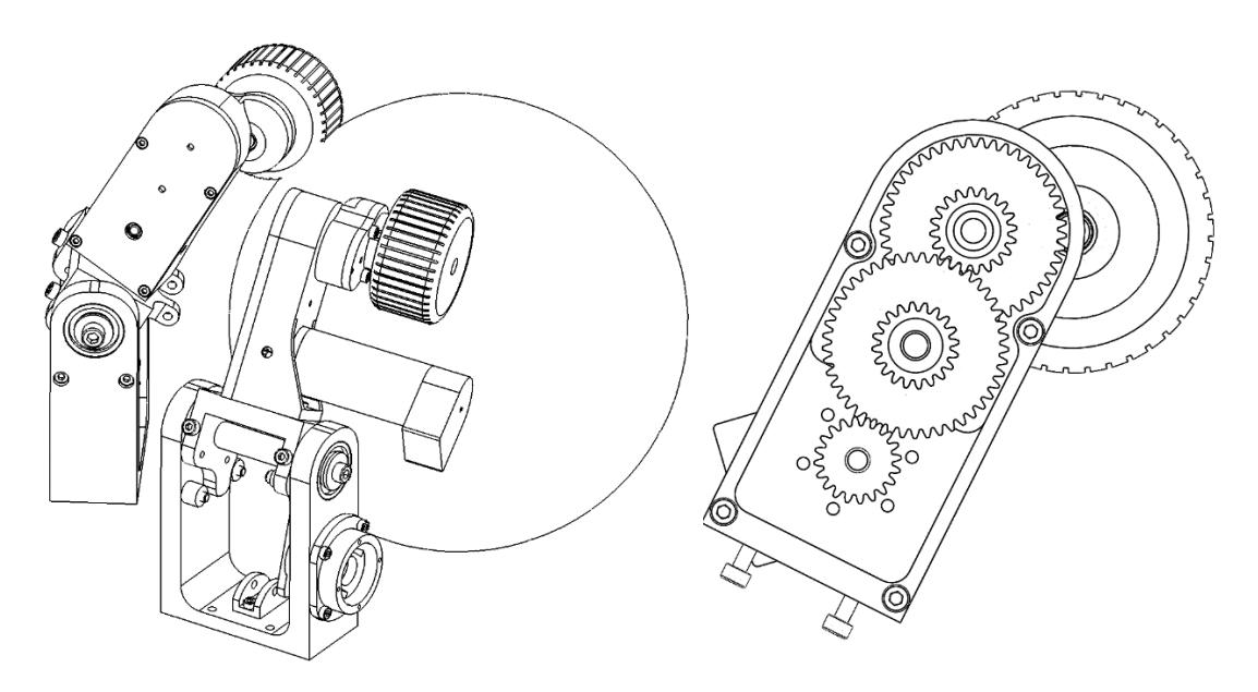
As mentioned before, ball handler system needs more power in order to win the fights. In the previews design, worm gear reduction has been used to provide required torque for the wheels. But the truth is that only half of the power is available for the wheels and the rest is wasted due to the worm gear wear and its low efficiency. So, changing the reduction mechanism could be a perfect solution for this problem. In the new design, ball handler mechanism through a 3 stage spur gear box provides 40-watt output power which is nearly double of the previews mechanism.
2.4 Electrical Design
A new approach to design of new electrical system of MRL such as boards and the way of wiring in order to achieve the ease of accessibility of them with least complexity, is considered. So the close coordination among this part and the mechanic is obvious. The reduction of data rate transmission across laptop and electronic boards are handled on UDP platform. In the following sections we briefly explain current electronic accessories.
2.4.1 Power board
This module has a responsibility to distribute the power for all subsystems and turning the systems on and off. Also many parts circuit such as LAN to CAN, IMU, Drivers are under control of POWER board. It also supplies the voltage of Epos and decreases the noise, respectively. In fact, three 24volt batteries and one 48volt relay to generate the voltage, is prepared. Here no microcontroller is used but only the connection between batteries, boards and fuses are determined.
2.4.2 LAN to CAN board
Data on UDP (as a simple method of two-way connection and data propagation) would be achieved and transmitted to drivers in such a way that data from UDP will be converted to CAN and finally received by drivers. In addition, using serial port can carry the data to Epos driver, so the accessibility of drivers using serial is possible at any time which there is any CAN fault.
2.4.3 Spin back board
The control of two SPIN BACK motors which is responsible to read the currency, and ENCODER motor to manage the speed, torque and RPM are under supervision of the SPIN BACK board. It's also connected with laptop using UDP which receives the commands from laptop. In addition, the motor which is responsible to adjust the level of the kicker (UP and DOWN mode) is controlled by this board. It receives the data from positioning sensors (IR and KMA) and optical sensors to control the robot. Also this board is in connection with KICKER board which means the kick command and other data will be transmitted using this board.
2.4.4 Kicker Board
The kicker board is designed to control the high voltage. It has one MOSFET for charging and four for kicking. The board also contains MOSFET driver to turn on and turn off the MOSFET in nanoseconds which prevents damaging them. The control board of the kicker circuit is a state machine with two states. The process begins by polling Up the Kick-Flag signal by main processor (Laptop) at state one. A signal that called Kick-flag is entered to the component to set the desired kick duration. When a high logic value is read by microcontroller at state two, the kicking sequence is initiated. In this state the microcontroller holds the kick signal high for the specified period of time. Keeping up signal (Kick-command), with high level logic at the different times can be creating different Kick powers. This process takes about 18 seconds. For improving the performance of this operation, we need to reduce this time to about 5 ~ 10 seconds.
The main changes of the electronic part in compare with previous years indicates the higher performance of complete isolation and better separation of boards in order to perform in a better way.
3 High level control:
The high level control system receives predicted data from vision software and destinations from AI planner module and commands the robot to go to its destination. In this process, the path planning plays an important role and we have used the VORONOI as path planning algorithm [4]. MRL team uses a supervisory controller in order to minimize collision between teammates. The planed path is a set of points which begins with the initial point and ends with the target point. As a result, the robot goal becomes passing through some specified points with a desired speed at each point. Therefore, a lower level function is used to design the robot's motor input speeds that brings the robot from an initial position and speed to a secondary desired position and speed. This function should design motor inputs with a minimum time objective. Robot acceleration and speed is bounded and as a result, the bangbang strategy is used to design the minimum time speed commands. This strategy is explained in [5] we have used a similar algorithm. This strategy suggests that the robot linear speed and acceleration could be projected on x and y axis' and each projection leads to a goal point reaching time. This algorithm finds the projection that leads to the minimum reaching time.
This algorithm was used by MRL team in previous years. This year, we have improved this algorithm using an observation. We have observed that robot maximum acceleration value is less that its deceleration one. In pervious method, the maximum acceleration and deceleration values were assumed equal, however, we have adapted the bang-bang strategy using two different constants for acceleration limits. Consequently, the reaching time is decreased and the robot displacements are less time consuming.
One question is that can we improve the used method any further? The speed and acceleration limitation is originating from motors' speed and acceleration constraints. As a result, it is possible to transform the design of speed signals to motors' coordination. This way, the travelling time could be minimized and the deviations from robot final position and speed could be decreased.
In addition to changing acceleration limits, we have used a PID controller that compensates the deviations from the designed path and speed. We had some problems in computing the error derivations. The vision error derivations add delays which significantly decrease the controller robustness and performance. We have used MTi-28A53G25 motion tracker module to overcome this problem. This module measures the speed errors and as a result, the vision derivation delays could be eliminated.
References
- V.Rostami, S.Ebrahimijam, P.Khajehpoor, P.Mirzaei, M. Yousefiazar "Cooperative Multi Agent Soccer Robot Team," International conference in enformatika system science and engineering, Volume 9, November 25-27, 2005, ISBN 975- 98458-8-1, page 95-98.
- J.W. Choi, R.E. Curry, G.H. Elkaim, Real-time obstacle avoiding pathplanning for mobile robots, in: Proceedings of the AIAA Guidance,Navigation and Control Conference, AIAA GNC 2010, Toronto, Ontario,Canada, 2010.
- Nicolaj C. Stache, Henrik Zimmer, "Robust Circle Fitting in Industrial Vision for Process Control of Laser Welding", Proceedings of the 11th International Student Conference on Electrical Engineering, Prague MAY 2007.
- J.W. Choi, R.E. Curry, G.H. Elkaim, Real-time obstacle avoiding path planning for mobile robots, in: Proceedings of the AIAA Guidance, Navigation and Control Conference, AIAA GNC 2010, Toronto, Ontario, Canada, 2010.
- KritChaiso, KanjanapanSukvichai, Skuba Extended Team Description, 2011