RV-Infinity Team Description Paper 2017
Hidekazu Suzuki, Tetsuya Yoshida, Kaori Watanabe, Yudai Miyadai, Kojiro Omori, Teppei Fukumoto, Daiki Sakuma, Ma Yuehang, Yuya Tateno
Tokyo Polytechnic University, Japan; zerosoft Co., Ltd, Japan
Abstract In this paper, we introduce RV-Infinity team and overview of past robot, and describe recent development of hardware and vision system including self localization method.We have proposed the self localization method which generates the searching space based on a model based matching with white line information of MSL field, and which recognizes the robot position by optimizing the fitness function using Genetic Algorithm.And we performe verification experiment of self localization and verify the accuracy of the proposed method.
1 Introduction
RV-Infinity is the RoboCup Middle Size League (MSL) soccer team of the Tokyo Polytechnic University, Japan. Our team was founded in 2008. Our team has participated in the RoboCup Japan Open from 2009 to 2016. It won 2nd place prizes 2011 and from 2013 to 2016.
This paper describes our recent development. Section 2 is hardware structure, which is overview of our past robot, driving module, ball handling module and kicking module. In section 3, vision systems, which are omni-directional camera module, self localization and ball recognition, are described.
2 Hardware structure
Hardware overview and components including driving, ball handling, and kicking modules.
2.1 Overview of past robot
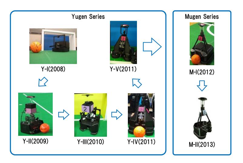
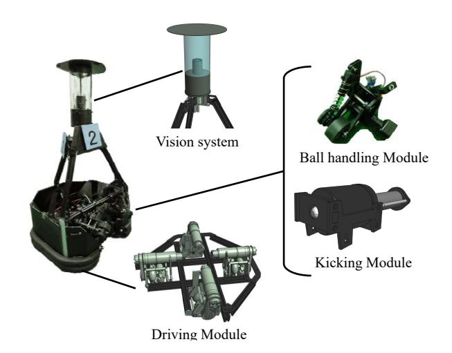
We have restructed the most part of hardware structure every year since our team was founded in 2008. Figure 1 shows overview of our past robot from 2008 to 2013. We developed the robot based on recent MSL concepts that are high torque driving module, ball handling module, electrical kicking module using solenoid and USB3.0 camera system. We have called the platform as "Mugen" series [1], and "Mugen II(M-II)" shown in Fig. 2, which is imoproved and based on "Mugen" model, participated in RoboCup Japan Open 2016.
2.2 Driving module
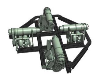
Figure 3 shows the driving module of M-II. This driving platform equips 4 wheels. Each wheel, which is omni-directional wheel, is driven by Maxon 150W DC motor throught a timing pulley with the ratio of 1:1 and a planetary gearbox GP42C with the ratio of 6:1. And, each motor is controlled by Maxon EPOS2 motor driver. The motor module consisted of wheel, pulley and motor is connected to base frame of platform throught a coil spring for stabilization of robot. This platform needs 48[V] power supply, and we use two 24[V] Ni-MH battery in series.
2.3 Ball handling module
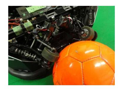
M-II has the ball handling module shown in Fig. 4 [2]. This module is consisted of a motor, Maxon 20W DC motor, and the roller made by silicon for rotating a ball with natural direction. The motor contorolled by Maxon EPOS2 motor driver and silicon roller are connected throught the gear box and timing pulley. And this module equips a damper for decreasing vibration of tha ball.
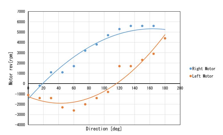
Figure 5 shows relationship of motor rev of ball handling module and direction that robot is moving In this figure, the vertical axis represents the motor rev [rpm] of left and right, and the horizontal axis represents the direction [deg] of robot. We verified the relationship by experiment.
2.4 Kicking module
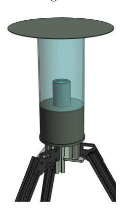
M-II has the kicking module shown in Fig. 6. This kicking module can shoot a ball with resin bar connected to the plunger of solenoid. The parameters that influence shoot speed and distance of the ball, i.e. wire diameter, coil diameter and length, stroke of plunger, etc., are determined based on various experiment. The determined parameters is shown in Table 1.
Table 1. Parameters of kicking module
| wire diameter | 2[mm] |
|---|---|
| coil diameter | 70[mm] |
| coil length | 60[mm] |
| stroke of plunger | 85[mm] |
3 Vision system
Vision systems including omni-directional camera hardware and self localization methods.
3.1 Hardware of vision system
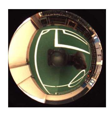
The vision system of M-II is consisted of the omni-directional camera (Point Gray Research, Flea3 [3]), a varifocal lens (Vstone) and a hyperboloidal mirror (Vstone). We developed vision system shown in Fig. 7 for RoboCup MSL robot by combining with above elements. The image captured by this vision system is shown in Fig. 8, and the image size and frame rate are 512 x 512 [pixels] and 30 [fps] respectively.
3.2 Self localization
We employ a white line of MSL field for self localization. We have proposed the self localization method which generates the searching space based on a model-based matching using white line information, and which recognizes the robot position by optimizing the fitness function which has the correct robot position as the maximum value of the function [4]. And this proposed self localization method employs Genetic Algorithm (GA) [5] for optimization of the fitness function.
3.2.1 Searching model
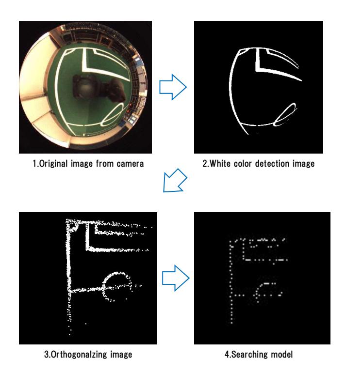
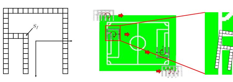
Figure 9 shows the process of making the searching model of the proposed method. At first, we need the detection image of the white line for making the searching model based on the white line. We obtain the white detection image by employing the converting method of color space from RGB to HSV and to YUV. And we generate the field information by orthogonalizing the white line information. Moreover, we determine the searching model by thinning down the field information based on white line.
3.2.2 Model-based matching
The proposed self localization method generates the searching space by model based matching between geometric information of the white line in the MSL field and above-mentioned searching model. Let us denote the set of pixels, which compose of the searching model shown in Fig. 10, as $S_f$ . The position $\tilde{\tau} = (\tilde{x}, \tilde{y})$ and orientation $\tilde{\theta}$ of searching model in the image is represented as $\tilde{\phi} = [\tilde{x}, \tilde{y}, \tilde{\theta}]^T$ . Then $S_f$ movement in the matching area is expressed as $S_f(\tilde{\phi})$ . And, if the pixel value of field image corresponding to the area of the moving model is expressed as $p(\tilde{\tau}), \tilde{\tau} \in S_f(\tilde{\phi})$ , then the evaluation function $F(\tilde{\phi})$ of the moving model is given as follows.
$$F(\tilde{\boldsymbol{\phi}}) = \sum_{\tilde{\boldsymbol{\tau}} \epsilon S_f(\tilde{\boldsymbol{\phi}})} p(\tilde{\boldsymbol{r}})$$
Also, we define $N_f$ as the number of pixels contained in $S_f$ . Then, the proper expression of $F(\tilde{\phi})$ is $F(\tilde{\phi})/N_f$ . The fitness function $F(\tilde{\phi})$ obtains the maximum value when the position of the searching model corresponds to the correct position that robot exist in the MSL field. Then, the problem of detection of robot position and orientation is converted to a searching problem of $\tilde{\phi}$ such that $F(\tilde{\phi})$ is maximized [6].
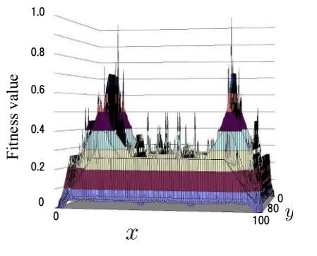
The calculation result of whole matching area shown in Fig. 11 shows Fig. 12. In this Fig. 12, the vertical axis represents the fitness value, and the horizontal axes represent the field plane. Here, we select only one depending on the value of an electric compass, because two maximum value exist in the function value caused by revolution symmetry of geometric characters of the MSL field.
3.2.3 Genetic Algorithm
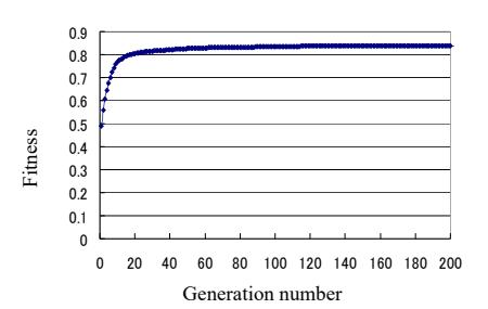
In the proposed self localization method, we employ Genetic Algorithm (GA) for searching the maximum value of the fitness function $F(\tilde{\phi})$ . A GA is an example of an artificial intelligence program and is well known as a parallel search and optimization process that mimics natural selection and evolution. In the proposed method, an elitist model of a GA that preserves the best individual in the population at every generation is utilized and genetic coding using gray code, roulette selection and one-point crossover are employed. And, the parameters of the GA process are determined by previous experiments. Figure 13 shows the result of the convergence of GA in case of self localization experiment using actual image that the robot captured at voluntary position. In this figure, tha vertical axis represents fitness value of fitness function, and the horizontal axis represents the generation number of GA. The GA converged the maximum value, which means currect position of robot in the MSL field, at about 60th generation in real time.

3.2.4 Verification experiment
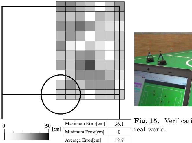
We performed the self localization experiment to verify the effectiveness of the proposed method. Figure 14 shows the result of the verification experiment that checked the self localization error between correct position and detected position at the quater area of the MSL field and at interval of one meter. In this figure, each box represents the error as the brightness of gray scale. Average error of this experiment was 12.7[cm], and the accuracy of the self localization by the proposed method is enough to play soccer.
Moreover, we performed the experiment using five player shown in Fig. 15 on the assumption of MSL game. Laptop PC displays the position sended by each robot in real time, and the positions of five player described in the result image corresponded with the actual position of the robots.
4 Conclusion
This paper introduced RV-Infinity team and overview of past robot, and described the recent development in M-II. We described the driving module, ball handling module and kicking module as the hardware structure. And We described the hardware of vision sysytem of M-II and self localization method and verified the effectiveness of the proposed self localization method using GA.
References
- Y. Yasohara, H. Suzuki, "Development of omni-directional mobile mechanism for RoboCup MSL", Proceedings of 31st Fuzzy System Symposium, pp. 151-152, 2015. (In Japanese)
- Y. Yasohara, K. Shimizu, H. Suzuki, "Development of ball handling mechanism for RoboCup MSL", Proceedings of 30th Fuzzy System Symposium, pp. 616-617, 2014. (In Japanese)
- Point Grey, "Flea3(USB3 Vision Camera)", https://www.ptgrey.com/flea3-usb3-vision-cameras
- T. Yoshida, H. Suzuki, Real-time self-localization for RoboCup Middle-Size-League, Proceedings 32nd Fuzzy System Symposium, pp. 397-398, 2016. (In Japanese)
- D.E.Goldberg, "Genetic Algorithms in Search, Optimization and Machine Learning", Addison-Wesley, 1989.
- H. Suzuki, M. Minami, "Visual Servoing to Catch Fish Using Global/Local GA Search", IEEE/ASME Transactions on Mechatronics, Vol. 10, No. 3, pp. 352-357, June, 2005.