Robot Club Toulon Team Description 2022
T. Kergourlay, T. Wemaere, A. Meaudre, X. Chereau, M. Jamme, G. C. Nelson, M. Dhainaut, M. Thomas, B. Talaron, C. Bohler, Y. Masinski, T. Mottay, A. Bassiouny, V. Garg, A. Elsayed, H. Elkholy, S. Ahmed, N. Hinden, D. Peloux, V. Hugel, T. Soriano, V. Barchasz, V. Gies
Université de Toulon, Avenue de l'Université, 83130 La Garde, France
Abstract Robot Club Toulon Middle-size league (MSL) team is a young team aiming at participating in the RoboCup 2022. For this edition, our robots have been entirely redesigned. This paper explains the major changes in our robots, and focus on changes that have not been tested yet by the MSL RoboCup community.
1 Introduction
Robot Club Toulon is representing University of Toulon, France, in the RoboCup Middle Size League (MSL). The team will be participating in the Middle-Size League for the second time in real conditions.
Our team has been participating to the RoboCup for the first time in Sydney 2019, with a second place at the technical challange 2021 and a third place at the scientific challenge 2021, and to several other robot competitions for the last 5 years, with 4 national titles in the French Robot Cups.
At the moment of writing this paper, RCT team consists of 1 PhDs, 8 MSc, 8 BSc, 4 staff members including 3 researchers in electronics and robotics and an engineer. For this edition, our robots have been completely redesigned according to a survey among other teams that has been done during RoboCup 2019 in Sydney. Several major changes have been decided this year, this paper will focus on them :
- Electronics and Software architecture.
- Mechanics : 4-wheels omnidirectional plateform.
- A new method for positioning and detecting balls and opponents.
- Multiple coils kicking system for increased ball speed.
To go deeper in the details, all our mechanics and electronics are fully described in the Mechanical and Electronic Presentations.
2 Electronics and Software architecture
2.1 Electronics
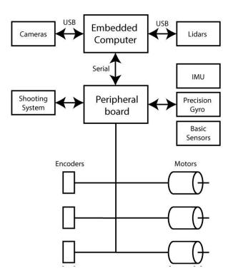
Electronics architecture of our robots is bio-inspired. The whole system is piloted by a Neousys Nuvo-7160gc embedded rugged computer acting like a cortex and doing intelligent tasks. This cortex is connected to another board acting as an autonomous nervous system, and doing repetitive and high frequency tasks such as sensor and motor management as shown in Fig. 2. This second board embeds a Microchip DSP having hardware peripherals for multi-threading tasks at a low level.
Complex tasks such as LIDAR scene analysis and artificial intelligence for strategy are embedded in the computer. A major change in 2022 is the use of 4 smart cameras (JeVois Pro) embedding artificial intelligence tasks such as image segmentation using deep learning in real time. High frequency motor control and sensors management is performed with a DSP using high speed interfaces such as USB, SPI or UARTs for synchronizing up to 20 different peripherals. The kicking system is a third board, independent for development and safety reasons due to high voltage.
2.2 Software architecture
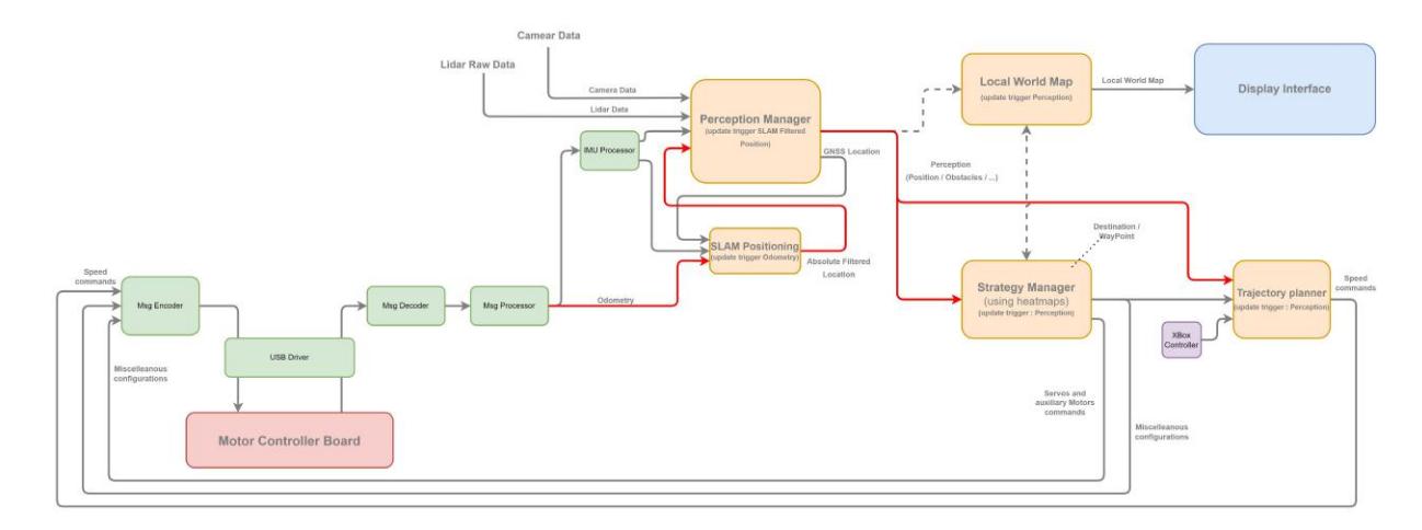
RCT robot software architecture is described at Fig. 3. Our robots no longer use a base station, each one acting as an autonomous player, even for decision tasks.
Code is divided in 2 parts corresponding to the 2 main electronics parts :
- Code is written in C for the motor and sensor control board based on a Microchip DSP 16-bits controller.
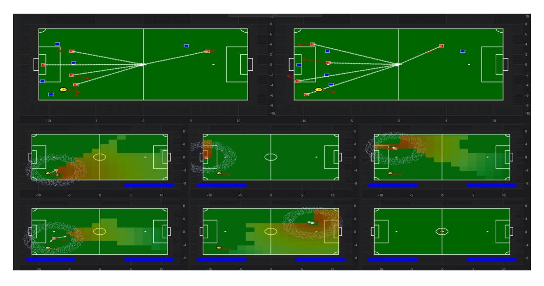
- For the cortex part embedded on the computer, code is written in C#. It is a fully event driven code with more than 40 independent modules linked together like a Matlab Simulink model. This way of coding allows students to work on small parts of the robot without having to know most of the code. It also allows to use the modules in multiple configurations such as the robot itself, or a simulator for the whole team and another opponent team (Fig. 4). This method allows to increase the reliability of each module.
3 4-wheels omnidirectional plateform
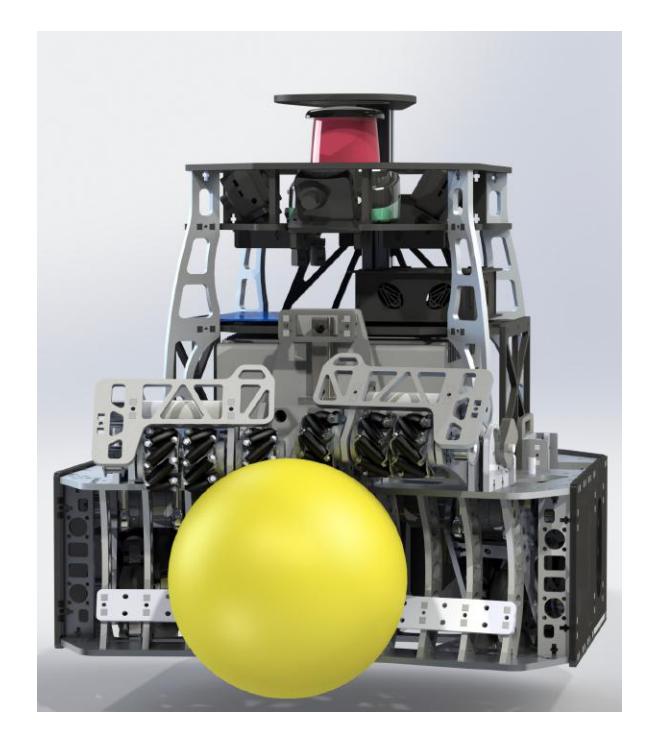
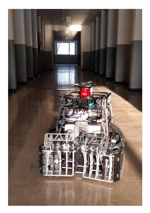
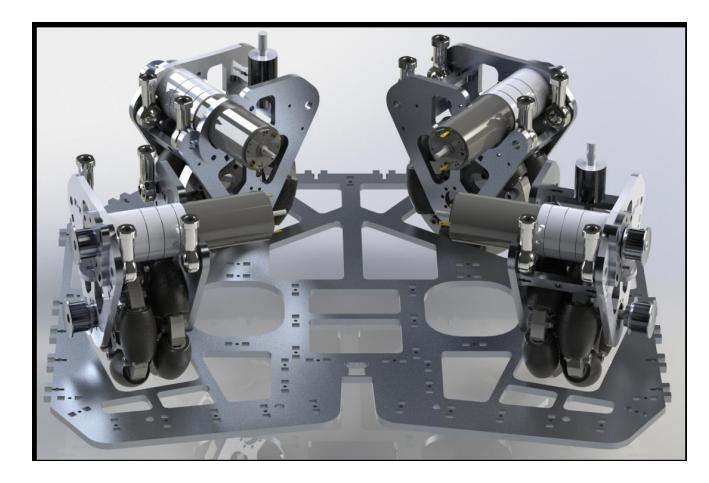
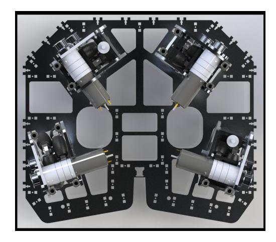
Major update this year, our robots are using a 4 wheels platform, with four wheels placed at four out of five vertex of a regular pentagon.
This evolution has been decided considering during a strong acceleration, most of the robot weight is pushed on the rear wheel as shown on this slow motion YouTube video featuring our robots. If acceleration is important, the front wheels will not be always in contact with the ground. In this case, using a 3 wheels robot is a real issue because the rear wheel doesn't transmit any strength and the robot can be out of control. Using a 4 wheels platform allows to keep control of the robot in any situation with always 2 rear wheels transmitting strength in contact with the ground. As shown on the video, even when the robot front wheels are not in contact with the ground, the robot is still under control and continues to accelerate.
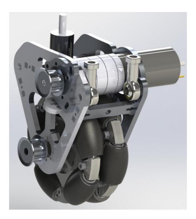
However, the drawback when changing from a 3 wheels to a 4 wheels platform is that this type of platform is not isostatic, thus it is necessary to add some springs / damplers in order to ensure that all the wheels are in contact with the ground in a normal situation as shown in Fig. 6. In our design, spring is the silent block which can be seen at the rear top in black on the picture.
Moves done with this solution are much more reactive than the ones done with our 2019 3 wheels platform using identical motors, especially during strong acceleration phases when the robot tends to pitch up as explained before, or during hard braking phase. This choice also allow to use the robots on a sliding floor for tests and exhibitions.
4 A new method for positioning and detecting balls and opponents
Omni-vision systems using mirrors are used by most of the teams for localization using the field lines and for opponent and ball detection and positioning. In 2019, our team also built an omni-vision system using a revolution mirror.
If these systems are relevant for finding the ball, they have some drawbacks for positioning our robot. A major one is the need for a precise alignment of the mirror and the camera. A small (less than 0.5mm) misalignment involve an important distortion in the omni-vision image leading to a wrong positioning. A second one, related to the first one is that the size of the field lines located far from the robot is very small in the image. Consequently positioning of the omnidirectional optical axis in a perfectly vertical direction is also very important.
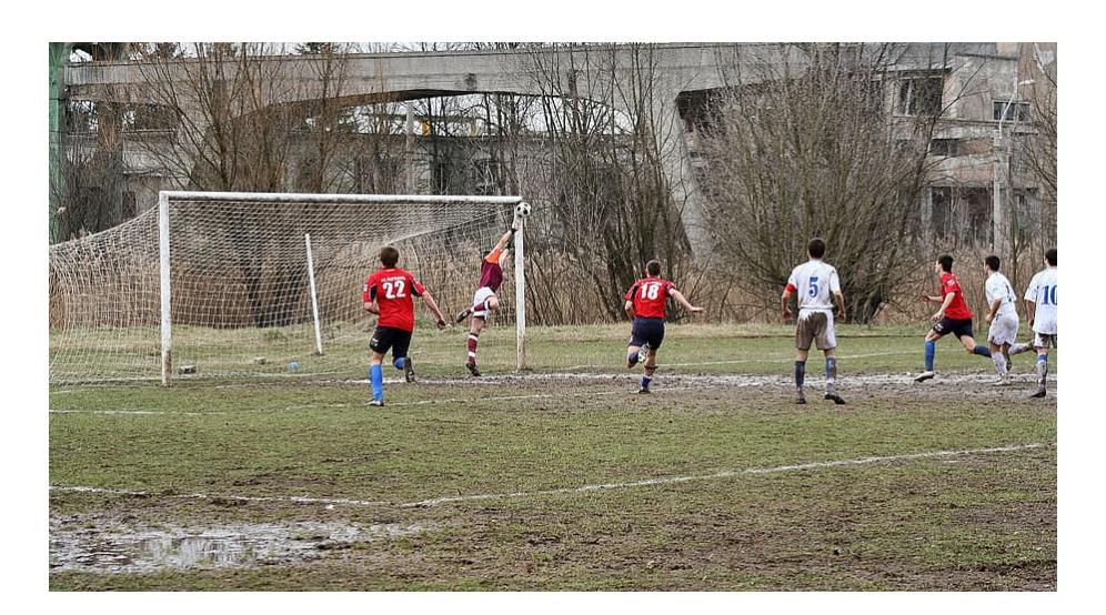
These drawbacks are limitations to the use of these omnidirectional systems. It is still possible to cope with them when playing on a green flat carpet, but it would be very difficult to cope with them when playing in real conditions such as the soccer field in Fig. 7. In this case, the robot couldn't be horizontal at any time and the lines are occluded by mud and field irregularities. This demonstrates that positioning using omni-vision is probably not a robust and reliable option in a long term view, if we want to play against humans in real conditions.
Consequently, the important question is : what is a robust soccer positioning based on ?
An answer to this question can be found by looking again to the picture 7. The view is a soccer player one. In this case, just by seeing the scene, a soccer player can tell that he is approximately at 30 − 35m from the goal and can evaluate it positioning zone quite precisely. This human evaluation does not use the field lines, which are difficult to see. The most important information is the place and appearance of the goal in the image, and on the perception of depth using stereovision. The size of the goal in the image gives a good estimation of the distance, and the ratio post size divided by crossbar size gives a good indicator to approximate the angle between the player-goal line and the goal-field center line. Indeed, goal posts direction is normal to the optical axis, so their height in the image is not projected and is inversely proportional to the distance from the player. Goal crossbar is not perpendicular to the optical axis in most situations, consequently its size depends on its projection angle. If the second goal can be seen, accurate positioning can be done easily because both goal angles and distances can be evaluated, leading to a multiple redundant information.
Having concluded that the goal is the most important thing to find in a soccer field for positioning, the question is now : how can we find the goal position in the scene ? Two options for finding the goal have been tested this year by our team.
4.1 Analysing image using cameras with deep learning
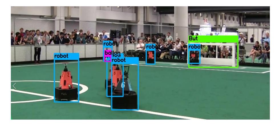
Using a camera with deep learning labelling and bounding box algorithms such as Yolo V3. In our case, learning has been done using Nubot MSL RoboCup image repository, adding several additional images taken during RoboCup 2019. Different classes have been labelled and learnt : robots, balls and goals. Results are shown on Fig. 8. There are a very few false positive detections of goals using Tiny Yolo V3 or Mobile Net SSD, and it works in real time on our cameras, each one embedding a Coral Tensor Processor Unit (TPU) form Google and a Neural Processing Unit (NPU) .
Benefits of cameras are the following ones :
- All the visible data in the scene can be used. In particular, properties of the objects can be used to find and classify them.
- Images are not transmitted by the smart cameras, reducing the overhead of the central computer.
Drawbacks are the following ones :
– Exact position and size of the goal can not be calculated with a centimetric precision using Yolo.
– Depth information in the scene is not available and can not be used for object detection and classification.
4.2 Finding goals using a high performance lidar
Using a Lidar is a second way for positioning robots in the field using the goals. There are also interesting features and drawbacks in this solution. Benefits are the following ones :
- Precision in distance measurement is excellent, which is approximately 1cm.
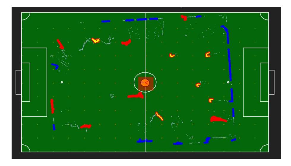
- Finding protruding and background objects in a scene (posts, opponents, walls...) is simple because transitions in measured distances can be used. Fig. 9 shows a reduced size game scene captured by our lidar, with some real-time post processings. In red (and yellow) are the protruded objects, in yellow are the protruded objects having a size compatible with a post size, in blue are the background objects.
- Angular resolution can be higher than angular resolution of a camera. For exemple, a OMD30M-R2000-B23-V1V1D-1L Lidar from Pepperl+Fuchs, one of the best ones in terms of resolution at this time, have a 0.014° angular resolution. In comparison, a 1024 pixels camera with a 135 vision angle have an angular resolution of only 0.13, 10 times less than a lidar. This is important in our case, because a goal post have a angular size of 0.35° when they are seen from 20m. Using a 1024 360° camera, the post width is only 2 pixels, whereas using a high resolution lidar, the post width is 20 points.
- Post processing doesn't require a high computational power. The number of points of a Lidar, event for a top-end one is limited. Using a OMD30M-R2000-B23-V1V1D-1L having a 0.014° of angular resolution leads to have 26000 points at 50Hz, compared with 2 million points at 40 Hz using a camera. Consequently, computations are approximately 100 times lighter using a lidar, avoiding the requirement of a GPU board. As an exemple, computation of the lidar map shown in Fig. 9 requires les than 1% of our computer ressources.
Drawbacks are the following ones :
- A Lidar make measurements only in one plane : in our case, the verticality of post is not used for detecting and classifying them.
- It is impossible do detect the ball with a lidar.
These different approaches for absolute positioning using the posts have been tested and are reliable. Using a lidar gives the best results and is an efficient way of positioning with a high precision, but there a probability of not being able to distinguish the posts among the protruded objects in some situations. In this case, adding a camera helps to locate approximately the goal in order to add some information in order to eliminate candidates found in the lidar data, leading to a precise and robust positioning.
This camera can also be used for finding the ball using conventional processing such as HSV color detection if the ball is a yellow one, but can also be used for finding any type of ball using deep learning algorithms trained on a dataset containing many different soccer balls.
5 Multiple coils kicking system for increased ball speed
An optimization of the structure of the kicking system has been implemented this year in order to increase the kicking speed. Speed of the ball propelled by the electromagnetic launcher (EML) highly depends on the structure of the coil gun, the sequence for triggering it, the initial position of the iron plunger and the size of its non-magnetic extension.
Among these parameters, the number of coils present in the kicking system have been optimized. For that we have studied coil gun implementations having 1, 2, 3 or 4 coils, with a fixed overall size and quantity of copper, as shown in Fig. 10. It is important to note that between each coil, an iron plate have been placed in order to close the magnetic circuit around each coil as much as possible.
As shown in Table 1, increasing the number of coils allows to transfer more power to the ball. Increasing the number of coils from 1 to 2 coils allows to increase the speed by 18%, corresponding to an energy transfer optimization of 40%. Combined with an optimization of the plunger initial position, the plunger extension length and the firing sequence, using a 2 coils EML is 104% energetically more efficient than the reference situation of an existing coil gun, without adding too much mechanical, electrical and algorithmic complexity to the EML.
Moreover, we prove that having a higher number of coils is not necessary for optimizing the energy transfer. In our case, having 2 coils in the EML is an excellent trade-off between energy transfer optimization and system complexity. Furthermore, robustness in terms of sensitivity to the coil triggering sequence decreases with the number of coils beyond 2 coils.
Detailed results have been published in an article submitted to MDPI Applied Science Journal and experiments in real conditions have been done several times : obtained kicking speed using 2 capacitors of 4700µF (twice the value of the paper) is more than 60km/h, with a dispersion of less than 20cm at a 8m range.
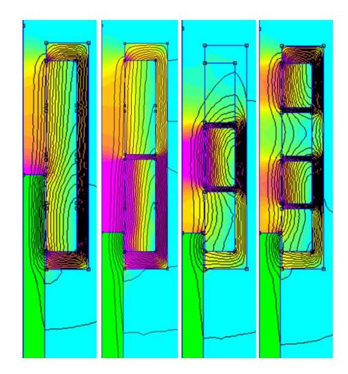
Table 1. Optimal ball speed depending on the number of coils in the EML
| Number of coils | 1 | 2 | 3 | 4 |
|---|---|---|---|---|
| Optimized ball speed (m.s⁻¹) | 13.5 | 16 | 16.1 | 16.3 |
| Kicking range (m) | 18.6 | 26.1 | 26.4 | 27 |
6 Conclusion
Participating in the RoboCup is a challenge for our young team. A strong emphasis has been put on the game this year. Everything is ready now for playing as a team having a basic strategy.
Thanks to the help of other teams, it has been a great adventure since 2019, and we are proud to have now a robot almost functional and to have developed some novel ideas for the MSL community.
Our challenge this year is to be able to play games against opponents, but it is still a real challenge for us !
References
- Meessen, K.J., Paulides, J.J.H., Lomonova, E.A.: A football kicking high speed actuator for a mobile robotic application. In: IECON 2010 - 36th Annual Conference on IEEE Industrial Electronics Society. pp. 1659–1664 (Nov 2010). https://doi.org/10.1109/IECON.2010.5675433