BARELANG63 Team Description 2023
Hendawan Soebhakti, Senanjung Prayoga, Rifqi Amalya Fatekha, Yogy Pratama, Nyoman Krisna Prebawa, Nawwafal Dzaki Musthofa, Wanda Eka Kurniawan, Muh. Yusup, Nadhif Suherryman, Muh. Revalba Ginggang, Muh. Sabiqul Himam, Tajdar Hal Ata, Mochamad Rizal Fauzi, Ridwan Bahari, Haidar Afnan Fakhruddin, Fahri Rahmat, Rizqy Pratama Singarimbun, Rafles Geovany Limbong, Muhammad Imron Shodiq
Barelang Robotic Artificial Intelligence Labs (Brail); Politeknik Negeri Batam Jl. Ahmad Yani, Batam Centre, Batam, 29461 Kepulauan Riau, Indonesia
https://brail.polibatam.ac.id/Barelang63/index.html
Abstract This paper describes the BARELANG63 Middle Size robot soccer team for qualification to RoboCup 2023. During the last year, improvements have been made in a significant number of components of the robots. The most important changes include improvements to the kicking system, vision system, local, communication between robots, and game strategy.
1. Introduction
BARELANG63 is the RoboCup middle-size league (MSL) football team from the Batam State Polytechnic, Indonesia. The project involved students, staff, and former members of the BARELANG63 team for the development of all mechanical components, from hardware to software. The BARELANG63 squad was founded in 2016 to carry out developments in the field of robotics, especially in the Middle Size League branch. BARELANG63 has participated in several national and international competitions, including the Indonesian robot contest, the RoboCup world championship (5th place in 2022), and the Asia Pacific RoboCup (2nd place in cooperation challenges). This paper describes the robot platform, the technology used in the robot, and the development of the robot from the previous year. Part 2 introduces the BARELANG63 soccer robot. Then, section 3 describes the improvement of the robot kick system. Part 4 describes the vision system of the robot platform. Section 5 shows the communication of our robots. Part 6 describes the strategy play of the robots. The last section is the conclusion of this paper.
2. Robot Platform
BARELANG63 used the robot last year. In this section, we will treat the BARELANG63 robots. Section 2.1 will introduce the hardware for this platform, while section 2.2 will describe the software.
2.1 Hardware
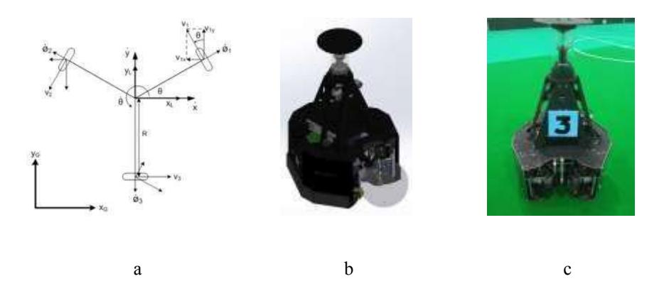
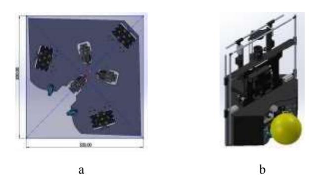
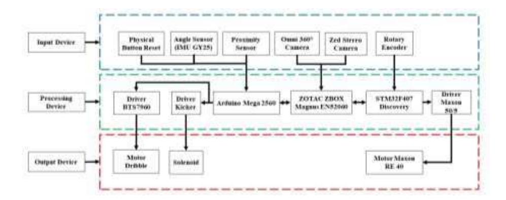
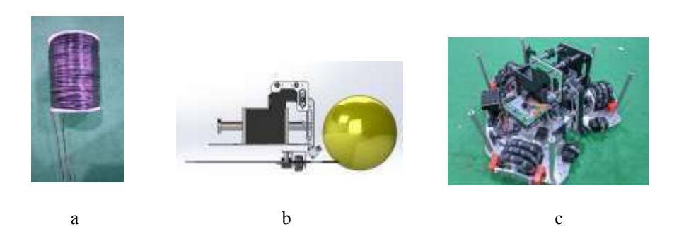
The robot mechanic system is built with three omnidirectional wheels, allowing it to move forward, backward, or surprisingly diagonally. The robot measures 48 x 47 x 75 cm. The whole robot body is built of aluminum and PLA+ filament. BARELANG63 robots use three Maxon RE 40 Ø40 mm Graphite Brushes 150 Watt motors as the robot movement, two high-speed DC motors with a diameter of 28 mm for the ball grip, and a solenoid as the ball kicker. We also use three external encoders on the bottom of the robot to determine the robot's position. The BARELANG63 striker robot uses three omnidirectional wheels with a configuration like in figure 1(a). This configuration allows the BARELANG63 robot to move in all directions to control the movement system then the kinematic equations are used at the local coordinates and global coordinates.
2.2 Software
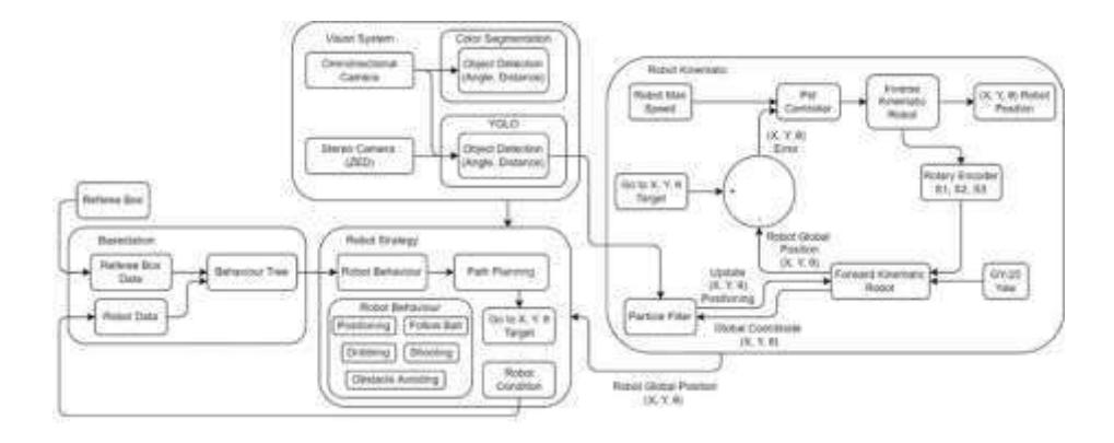
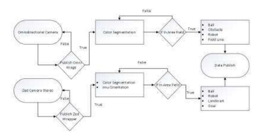
Figure 4 describes the BARELANG63 software section. The software part consists of the vision system, strategy, base station, and kinematics. Color segmentation has been used as vision systems programmed in Python. The data obtained from the vision will be used as input for the localization system and robot algorithm strategy, not only from the vision system but also from robot kinematics, team coordination, and data from the base station. Robot strategy processing will produce a robot trajectory planning system to act as a kinematic system according to the soccer strategy.
3. Improve Kicking System
The solenoid mechanism is used as a kicking system for robots controlled by the Arduino Mega 2560. The kick strength of this system depends on how wide the pulse is input as the trigger gate on the IGBT. The kicking leg on our robot is not fixed and it can be set for flat kicks and lobs. For the kicking leg mechanism last year we adopted the CAMBADA team kick system, where there are two kicking feet for flat kicks and lobs[2]. This kick system has many drawbacks, including weak kicks, monotone kick modes, flat kicks only, and lob kicks. To cover the shortcomings of this system, we adopted the kick system used by the Tech United team which only uses one kicking leg to make it more flexible in its kicking mode[3]. In this kicking leg system, we can adjust the kick so that it is not too high, the lob kick is so high to get past the obstacles in front of the robot when it is about to pass, and the kick is flat. We developed a kick system aimed at getting a greater variety of kicks and increasing the power of the robot's kicks. We also recalculate the manufacture of solenoids which function to reduce the load generated from the kicking system and increase the robot's kick power.
4. Vision
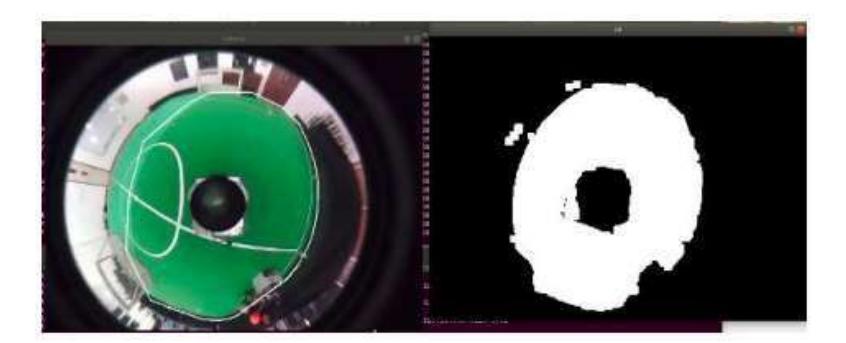
The 360-degree viewing angle of the omnidirectional camera function allows it to locate objects. The ROS-based image technique publish is used to publish camera captures. Subscribe to the color segmentation area for the camera publication yield. In order to maximize the number of detected objects in the form of balls, fields, robots, and obstacles, the Morphology Transformation Method, RGB Convert Image, Kalman Filter, Gaussian Image, Thresholding, Angle Detection, and Distance Detection are used in color segmentation. The data is then sent using ROS publish messages.
4.1 Goal Detection
On the current goal detection system we have development. To detect the goal we use the color segmentation method, using filtering with open, erode and dilate morphology methods. This detection will later assist in the goalpost detection process, where the goalposts will be detected in the goal area.
4.2 Landmark Detection
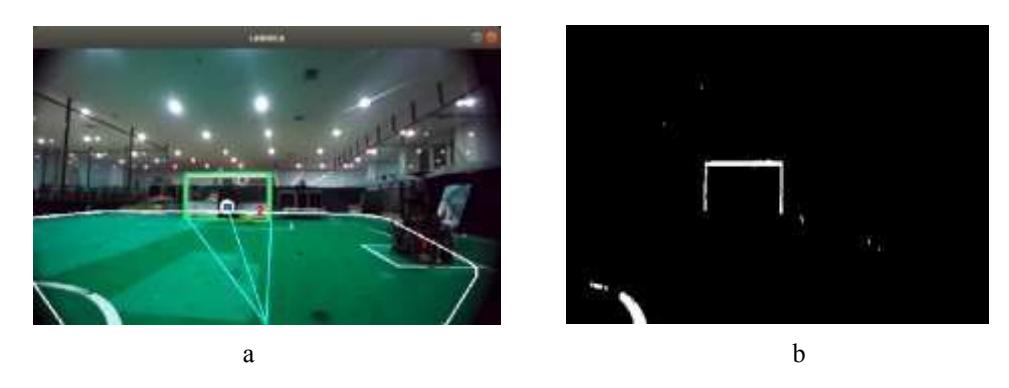
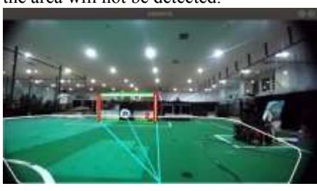
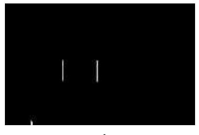
The vision system here is also experiencing development. Previously, to detect landmarks such as goalposts, we used a deep learning method using the Yolo v3 algorithm. This deep learning system consumes a large amount of computation so that the battery that supplies the PC runs out quickly and also requires data retrieval for learning which takes quite a long time. To overcome this problem we use the segmentation method to read the goalposts. This color segmentation detection system is applied to a stereo zed camera where it will read white pixels that are vertically positioned.
To avoid the whites that are outside the field being detected by the camera, we create area boundaries around the goal, so only the whites that are in the vertical position of the goal area will be detected by the camera, the whites that are outside the area will not be detected.
4.3 Imu Orientation
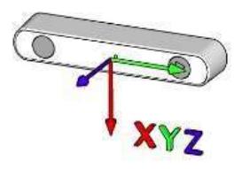
In the orientation system here, we are upgrading it using the orientation Imu sensor that is on the Zed stereo camera. The imu sensor on the zed camera has a smaller error value compared to the imu gy25 sensor. The IMU sensor from the zed stereo camera will certainly be useful to assist movement and reduce errors from the odometry robot.
5. Robot Communication
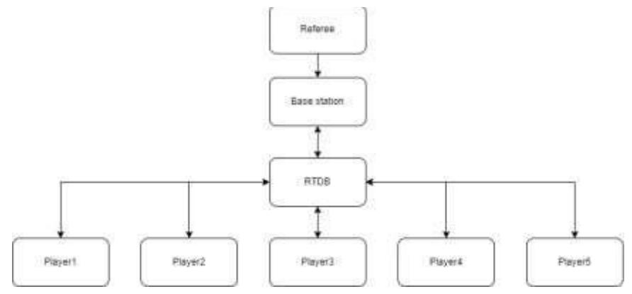
The communication system between robots that we use is RTDB which was developed by the CAMBADA team and the Falcon team. The RTDB communication system functions as middleware, namely for communication between programs in the local agent and communication with other agents[4]. RTDB is easier and more flexible to communicate between robots than using the UDP communication protocol because the data sent is in the form of a serialized structure making it easier to process the data. Meanwhile, for microcontroller programming communication with a PC, we use ROS communication where the microcontroller can act as a sender and receiver as well as communication on a PC.
6. Robot Strategy
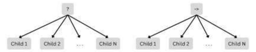
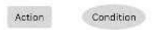
The BARELANG63 robot strategy uses basic strategies such as passing, ball handling, shooting at goal, avoiding obstacles, determining defenders, and determining attackers. Decision-making is done with the behavior tree algorithm, the behavior tree algorithm starts by executing each node sequentially, known as the control flow node, determined by the parent and child relationships. The signal to start execution is given to the root node, with a specified frequency as necessary. After execution, the node returns the running value. If the execution successfully reaches its destination, it returns a success value; otherwise, it fails. The behavior tree uses two control flow nodes, sequence, and fallback, followed by two execution nodes, action, and condition. Sequence nodes are marked with "->" and start by executing child nodes from left to right. Execution continues with a failure or a running value depending on the step taken and succeeds if all child nodes return a success value, similar to the AND logic gate.
7. Conclusion
This paper describes current research on the development of capabilities and systems used in the BARELANG63 soccer robot from a mechanical, electrical, and software perspective. Some of the improvements that have been and are ongoing out include the first section, the goalkeeper robot building changes to the mechanical design and adding a kicking mechanism so that the goalkeeper robot can build up attacks. The second change is the robot's kick system, where last year the BARELANG63 soccer robot used a system of lob resistance and flat kick by moving the kicker's leg to the side, now the BARELANG63 soccer robot uses an up-anddown system where this system is more flexible in kick selection. The third is an improvement in the detection of vision robots, and now BARELANG63 has changed the system for detecting objects in the field using color segmentation. The previous detection method that our robot uses is the YOLO method, where the YOLO method requires heavy computation, so object detection requires a lot of power and processing. The third is an improvement in the robot communication system, previously the BARELANG63 soccer robot used the UDP communication protocol and has now switched to using the RTDB communication system where RTDB communication is easier and more flexible to communicate between robots than using the UDP communication protocol because the data sent is in a serial structure so that easier to process data.
References
[1] K. V. Utama, R. A. Fatekha, S. Prayoga, D. S. Pamungkas, and R. P. Hudhajanto, "Positioning and Maneuver of an Omnidirectional Robot Soccer," in 2018 International Conference on Applied Engineering (ICAE), 2018, pp. 1–5. [2] Bernardo, "CAMBADA 2013 new Platform." [3] B. P. T. van Goch, M. J. G. van de Molengraft, I. R. J. E. Merry, and R. Verhage, "Optimizing a solenoid for a Robocup kicker," University of Technology Eindhoven, 2006. [4] L. Almeida, F. Santos, T. Facchinetti, P. Pedreiras, V. Silva, and L. S. Lopes, "Coordinating distributed autonomous agents with a real-time database: The CAMBADA project," in Computer and Information Sciences-ISCIS 2004: 19th International Symposium, Kemer-Antalya, Turkey, October 27-29, 2004. Proceedings 19, 2004, pp. 876–886.