Team Description Paper (TDP)
Josh Rodgers, Ben Smith, Fedor Dakhnenko, Edwin Fernando, Advik Chitre, Lucas Ng, Awais Khawaja, Adrian Khoo, Jie Tan, Janice Chan, Thomas Godden, David Cai, Raihan Usman, Digo Yu, Haotian Wu
Imperial College London, London, SW7 2BX, UK
Abstract We are a new student-based team representing Imperial College London's Robotics Society. To our knowledge we are the first MSL team representing both London and the United Kingdom. Despite being new to the competition, we aim to bring innovative ideas and a disruptive strategy, and most importantly… have fun!
Imperial College Robotics Society Football Club ICRS FC
Imperial College Robotics Society Football Club ICRS FC

1 General Design Philosophy
As one of the newest teams in the MSL competition, it was clear that funding, time to develop and academic support would not be readily available to our new team. Within the framework of the university, ICRS FC wouldn't have access to expertise from researchers at the university - operating as a part of Imperial College Union's Robotics Society and not a departmental affiliation. In a sense this project would operate purely as an extracurricular exercise for students on paper and would have to fit into students' exam and coursework commitments realistically. On that premise, ICRS FC is a fully undergraduate team. Despite this, we believed we could contribute both originality and a disruptive element to the competition, and contribute to MSL's original mission statement, helping to push the state of the art and contribute new ideas and research. From the offset our design space was constrained significantly compared to other teams, and an original strategy was settled on early. The aim was to rush prototyping of a single robot, as a proof of concept. The robot characteristics that we could compete on would have to come at the cost of a compromise in other areas, due to our budgetary constraints. With that focus, a low cost, low mass platform was agreed upon. By reducing our mass (and the associated cost in motor price point and powering a heavier platform), we would be able to compete in speed when put against other robots in the competition. The computational strategy design path chosen was for a fast aggressive strategy. The priority would be on short fast passes, with an emphasis on keeping the ball in motion and low to the ground.
2 Testing Frame
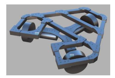
The primary focus was on a versatile, open and multi-use frame to act as a test bed for mounting the kicker, dribbler and visual strategy. The frame used lightweight aluminum extrusions and PLA 3D printed connectors.
3 Motor Selection
The drive base was designed to allow rapid movement in any direction. To do this a design using 3 omnidirectional wheels, each positioned 120 degrees from one another, was selected. Other configurations that would allow for greater speed in a single direction were considered, such as unequal separation of the motors radially, or even 4 omni wheel designs. Ultimately the flexibility of moving equally in 360 degrees was deemed more important, and the simplicity and cost of a 3-wheel system was preferred.
4 Motor Controller Stack, Microcontroller & Custom PCB
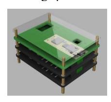
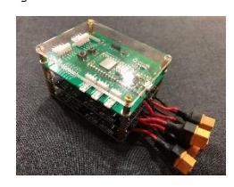
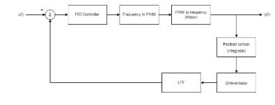
To implement this design in software a simple python script was created that would run on a mini PC and send commands to a microcontroller over serial. The microcontroller then runs custom firmware to interpret and implement the commands, such as moving individual motors, moving the whole robot at a certain speed and heading, and rotation. Combining these commands to move in an arc or other complex movements is also possible. The microcontroller that was chosen was the Raspberry Pi Pico W, which includes two ARM cortex M0+ cores running at 133MHz, as well as Wi-Fi. It was selected for its speed and low cost. The firmware on the microcontroller includes a real time operating system (freeRTOS) running a number of tasks, such as sampling sensors, processing samples, PID controllers, serial communication etc. The control scheme for the motor speed PID controllers is pictured below. There is another PI controller used to rotate the robot that uses the onboard inertial measurement unit (IMU) to calculate the heading and turn to face a new heading. All this functionality was first tested using breadboards and was then combined into a custom PCB to minimise space and weight and make it tidier. The PCB was designed to be the same size as the motor drivers, allowing the boards to be mounted in a stack, further increasing space efficiency.
5 Dribbler
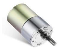
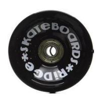
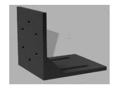
To achieve ball handling and ball receiving, a dribbling system is required to be designed. After considering and comparing various designs, a dribbling system with two parts is being developed. The active part consists of two motors attached with dribbling wheels, positing in front of the robot. The motor we chose is ZGB37RG, a 12V DC motor with 200RPM. For this system, the torque provided by the motor is significant as it is required to overcome the friction between the ball and ground. The dribbling wheels are also carefully chosen to achieve expected effects. To increase the friction between the dribbling wheels and the ball, the skateboard wheels made out of Polyurethane have been chosen. The motor bracket is also being designed to mount the motor onto the drive base. The passive part consists of two supporting wheels, they are planned to be installed in front of the robot and under the frame. Due to time constraints, we are still conducting research on designing the dribbling mechanisms and controls. One of the current ideas is adjusting the speed of motors depending on the distance between the ball and the robot. An ultrasonic sensor can then be implemented to detect the distance.
6 Kicker
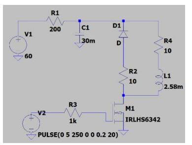
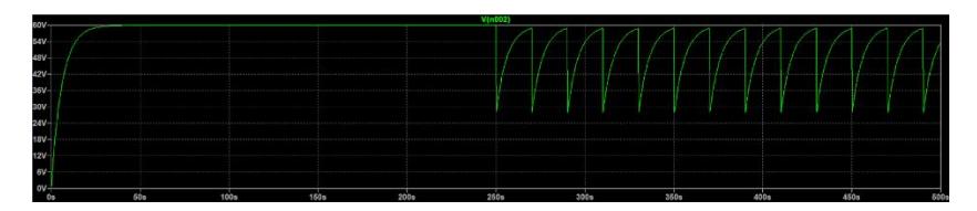
A variety of methods were considered for the kicking mechanism. The main requirements were size, reliability, complexity, and cost. The primary goal of the kicker was to store a large amount of energy that could be quickly released and transferred to the ball. One of the designs considered was a spring powered system. This would use a motor to wind up a spring to store energy. Since most parts of this system could be manufactured from basic materials, it would be relatively cheap. However, the mechanical stress would make it less reliable and durable. Another potential design considered was a solenoid. This uses a coil of copper wire as an electromagnet to accelerate a rod made from iron and push it into the ball. Fewer moving parts makes this more reliable, however the electrical components required would increase the cost and pose a potential safety risk. This was the method chosen in the end, with special considerations for safety taken to reduce the risks. The circuit uses a large capacitor to store energy. This way, energy can slowly be accumulated in between uses, and when required, a large, instantaneous current could be drawn to produce a powerful magnetic field for a short period of time. By storing more energy in the capacitor, it would be able to impart more energy per kick, and also store multiple kicks worth of energy. The energy stored in a capacitor is given using the equation: E= 12CV2. This meant either the capacitance or voltage could be increased to achieve a greater energy storage capacity. Increasing the capacitance would increase costs and the capacitor would take up more space. Increasing the voltage would require a more complex power supply and pose a potential hazard. Through extensive research and simulation, a value of 33mF at 60V was chosen. This provided the best trade-off between safety, cost, and charging speed. To achieve a voltage of 60V to charge the capacitor, a boost SMPS was utilized. This could take an input of 12V (from a battery) and produce an output of 60V (albeit at a low current). The circuit below was designed to charge the capacitor and control the discharge into the solenoid. It takes the 60V output of the boost SMPS and, through a 200Ω resistor, charges the capacitor. The solenoid is represented by an inductor with series resistance on the right-hand side of the diagram. A pulse generated by a controller such as an Arduino controls a MOSFET which, when activated, allows current to flow out of the capacitor, through the solenoid, and to ground. This rapid flow of current through the coil generates the strong electric field needed to kick the ball. The diode is necessary to carry any unexpected current generated by the inductor.
6.1 Simulations and Energy Analysis
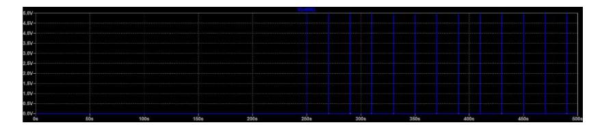
Simulations were carried out to explore the various voltages and currents during operation. A few of the resulting graphs are shown below.
6.2 Actuator Assembly
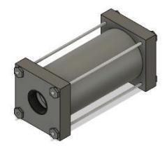
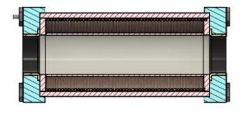
The actuator assembly consists of a coil of wire wrapped around a plastic tube. As current flows through the coil, a magnetic field is generated. This can be used to push a steel rod, discussed in a later section. The entire tube is then encased in a steel housing to concentrate the magnetic field and produce a more powerful kick. The images below show the design for the actuator assembly.
6.3 Plunger Design
This diagram shows the dimensions of the coil holder and cylindrical shell. The hollow white tube in the middle is made of plastic, as to not impede the magnetic field in any way. This then has a copper coil wound around it. On the outside is a steel tube to contain the magnetic field. Within each of the end caps is a low friction bearing that allows the rod that will sit in the middle to slide more efficiently. Holes in the corner of these caps allow threaded rods to pass through to screw the whole assembly together. The plunger is the rod that sits inside of the actuator and moves to kick the ball. It consists of a plastic part at the front, and an iron part at the back. The plastic section has an M3 thread drilled into it. The iron section has an M3 threaded rod on each end. This allows the two sections to seamlessly screw together and allows a set of washers to be screwed onto the end.

6.4 Energy and Performance Calculations
Initially the plastic section lies inside of the actuator and the iron section sticks out the back. When a current flows through the coil, a magnetic field is generated. This attracts the iron rod into the actuator, and therefore pushes the plastic section out of the front, pushing it into the ball. Based on research, we expect the efficiency of energy transferred to the ball to be around 5%. Given the simulations show a total of 45J is discharged from the capacitor per kick, this corresponds to 2.25J transferred as kinetic energy to the ball. Given a ball of 0.5kg, with a kinetic energy of 2.25J, we expect a final kicking velocity of around 3ms-1.
7 Omnidirectional Camera
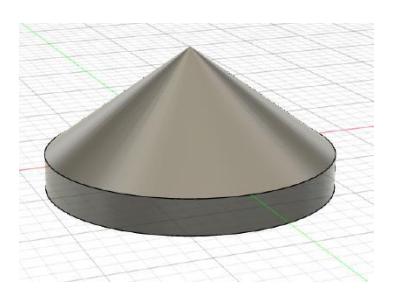
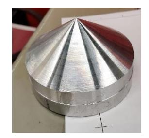
We needed a camera system that could give the main computer an idea of what each robot can see. We observed other designs for omnidirectional systems and followed suit by designing a reflective cone which can reflect light onto one point, where we can place our camera. This allows one camera to get a 360 view of each robot, without the extra image processing if we were to use multiple cameras per robot. The cone would be mounted upside-down with the camera pointing up to allow the camera to maximize the useful field of view. We had to choose an angle for the slope of the cone. A large angle would mean a steeper cone, therefore increasing the distance we could see but at the same time, reducing the amount we could see at close range. Other teams have dealt with this issue by having multiple angles on different parts of the cone, however this would add complexity and was not feasible for us, a new team. We opted for an angle of 36 degrees as this would give a good balance between close range and long range, while maximizing the surface area of the cone dedicated to medium range reflections. We then fabricated our design by using a lathe to cut an aluminum rod with 82mm diameter. The top layer was cut, leaving the pointy tip. The cone was then flipped so we could hollow the cone, reducing overall weight.
7.1 Design Finalization
This design was then sanded and polished to give a mirror finish so the camera could accurately capture the environment.
8 Image Processing
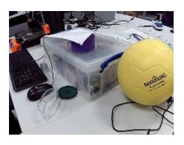
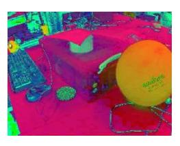
An excellent and cost-effective way of achieving 360° vision was to use a static camera and pointing at an apex-down conical mirror. The image was "unwrapped" using a function which mapped pixels to distances from the center proportional to the actual distance of the object. (Inverses of functions with several trigonometric terms needed to be computed. This was done through a symbolic computation program written in Haskell, capable of differentiating formulas, to generate the Taylor approximation of the inverse). Each frame of the video can simply run through the function and come out undistorted. After the image is "unwrapped" it is run through an object recognition system, which identifies objects based on their colors. For this purpose, the image is firstly transformed in the HSV (hue, saturation, value) system, which shows significantly better results when dealing with shades of the same color. After that a black and white mask of the image is created by setting boundary conditions for hue, saturation, and value for every pixel of the image, so that if a pixel's properties satisfy these conditions, it appears white on the mask image and black otherwise. The algorithm creates a mask for every color used in the match to identify the boundaries of the field and the goals (white color), the robots (black) and which team they are on (based on the color of the markers on them), and the ball (its color is set before the match).
9 Conceptual Strategy
When every robot has identified what it can see by applying several masks on the image from the omnidirectional camera, these bits of information can be combined to create a simulation of the field. The state of the game dictates what every robot should do next based on who possesses the ball:
- If an ally has the ball, the robots position themselves in such a way that they can pass the ball as frequently as possible, since the robots are lighter, hence, faster. This allows the team to slowly get behind the defense line to the goals.
- If an opponent has the ball, the robots position themselves to "mark" the closest opponent, preventing a successful pass to that robot, or blocking a direct shot to the goals if the opponent dribbles the ball.
- If no one controls the ball, then the robot, which is the closest one to the ball, tries to intercept it. At the same time other robots stay in the same formation (defensive or offensive, as described above), which they were before a team lost possession of the ball.
10 Platform Selection
Combining ubuntu with a low power mini-pc was the best path chosen. ROS2 was selected as the platform of choice for its versatility and expandability. In following our team's design philosophy, a lightweight computer was selected, with strong integrated graphics at an affordable price point and acceptable form factor. This would allow for competitive image processing without compromising on cost or increasing the height of the robots center of gravity. Using the more traditional approach of mounting laptops was considered but decided against because of the potential weight gain.
We installed Ubuntu and ROS2 onto our mini pc, adding our scripts to our ROS workspace. We learnt ROS using the turtlesim module, allowing us to simulate our robot before it was ready to be tested. We also planned to use Gazebo to simulate the environment so that we could implement machine learning.