Alzahra Soccer 3D Simulation Team Team Description Paper for RoboCup 2010
Maryam Davari, Fatemeh Sadat Makki, Bita Namvar, Elmira Asadzadeh, Seyedeh Atieh Hashemzadeh
Alzahra University Tehran, Iran
Abstract In this paper, Alzahra 3D soccer simulation team activities for RoboCup 2010 competitions is described. Since the number of agents in 3D soccer simulation is being increased each year, we use a path finding algorithm adapted from some Computational Geometry (CG) methods. Central Pattern Generator (CPG) provides in real time a reliable synchronization signal for periodic motions such as walking, respiration and flap. In most of the presented works the numerous CPG parameters are found using automatic techniques like Genetic Algorithms (GA).
Introduction
Alzahra university Robocup Team was formed in late summer 2009 in collaboration with students of mathematical sciences and computer engineering in technical college Alzahra university, with the aim of robotic science progress. In this short time our team could promote code (our code is based on Zigorat base code) and obtain useful skills for robot. Also, we optimized the skills using scientific methods and new techniques.
Team Architecture
The performances of humanoid robots depend on the agent's architecture. If this architecture is more accurate, the performance of the robot will be more like a human.
Here, we will briefly explain the architecture of our robots (Fig. 1).
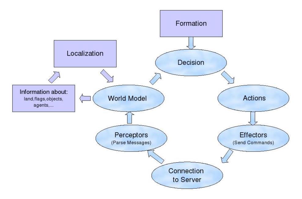
Formation
At this part, the position and also the role of each agent (goal keeper and players) is specified with regard to the type of playing (offensive, defensive).
World Model
It includes all needed information for an agent such as the information about the field, ball and the other agents in the game. Therefore, a robot can figure out his own location and the state of other objects in the field. World model updates this information in each cycle with the messages it recieve from the simulation server. The agents can always use the information stored in the world model to make their decisions.
Decision
This part specifies the role of each agent using the Formation (in the beginning of the game) and World Model (during the game).
Actions
After the decision making process, actions of robots (like walking, kicking, turning and standing up) are sent to the server as commands.
Send Commands
It prepares a connection with the server and sends information to it.
Server Communication
This part is about communication with the server that includes network control, messages analysis and fixing the commands. This part is very important because it performs sending commands to the robot and also receiving sensor information from the robot.
Preceptors
In this part, the server sends necessary information about the game, players and other objects that were seen in the field.
Localization
Since robots receive important information from the server such as the position of the ball and the other agents as relative positions, localization is one of the most important and basic required abilities of a robot.
Considering the 120 degrees field of view of the robot in each dimension, this subject has become more complex compared to the previous versions of the simulator in which robots had a 360 degrees vision. Previously, robots were able to find their own location by seeing at least 3 flags with their 360 degrees vision; but with the new restricted vision sensor, this is not always possible.
Here, to remove this problem we use a new method in which the robot can localize itself using at least 2 flags. An overview of this method follows: First, we calculate the robot's height with this method:
$$\begin{split} Z_R = FootSize_Z + ShankSize_Z \times cos(\theta_{rlj5} + ThightSize_Z \times cos(\theta_{rlj4} - \theta_{rlj5}) \ + (TorsoHeight + Head_Z/2) \times cos(\theta_{rlj3} - \theta_{rlj4} + \theta_{rlj5}) \end{split}$$
$$Z_L = FootSize_Z + ShankSize_Z \times cos(\theta_{llj5} + ThightSize_Z * cos(\theta_{llj4} - \theta_{llj5}) + (TorsoHeight + Head_Z/2) * cos(\theta_{llj3} - \theta_{llj4} + \theta_{llj5})$$
Since the final height of the robot is relative to its base leg, we can use the value of the FRP sensor to determine the robot's base leg and use this height as the height of the robot. Now, since the height of the goal posts is different from the corners' height, we divided the visual states to 3 modes to simplify the flag vision control:
- Right and left corners are visible
- Up and down corners are visible
- Left and right goal posts are visible
The difference between the first and the second states is the method of calculating the x coordinate in one state will result in the y coordinate in the other state. The third state is further divided into 2 substates:
– When
$$G2L_Y < y < G1L_Y$$
– When
$$(y < G2L_Y) \land (y > G1L_Y)$$
In these cases with 2 visible flags, robot's locus around each flag is available which is equal to a sphere with the flag in its center and the relative distance of the flag as its radius. Then we calculate the locus of the meet area of two obtained spheres and find the total radius. Since we have the robot's height, we can obtain x and y coordinates.
Until now, x, y and z coordinates of the robot are known but its angles relative to these 3 axes should be found. One simple procedure to find these 3 angles (θ, ϕ, ψ) is achieved by using hinges angles of robot and relative angle which is seen from one flag.
$$\theta = tan((Y_{flag} - y)/(X_{flag} - x)) - \theta_{flag} - \theta_{neck}$$
$$\phi_R = \theta_{rlj3} - |\theta_{rlj4} + \theta_{rlj5}|$$
$$\phi_L = \theta_{llj3} - |\theta_{llj4} + \theta_{llj5}|$$
$$\psi_R = |\theta_{rlj2}| + |\theta_{rlj6}|$$
$$\psi_L = |\theta_{llj2}| + |\theta_{llj6}|$$
Final ϕ, ψ are related to the base leg which is determined with the procedure mentioned before.
As the previous discussion, this solution is applicable only with two flags. If the robot can't see 2 flags, it can find them by rotating its head.
Path Finding
One of the important problems concerning mobile robots is reaching a target without hitting obstacles (players and other objects in the field). Normally, Artificial Intelligence (AI) is used to help robots avoid obstacles, but another possibility is to use Computational Geometry (CG) methods. In our team, we are working on a CG based approach to the path finding problem.
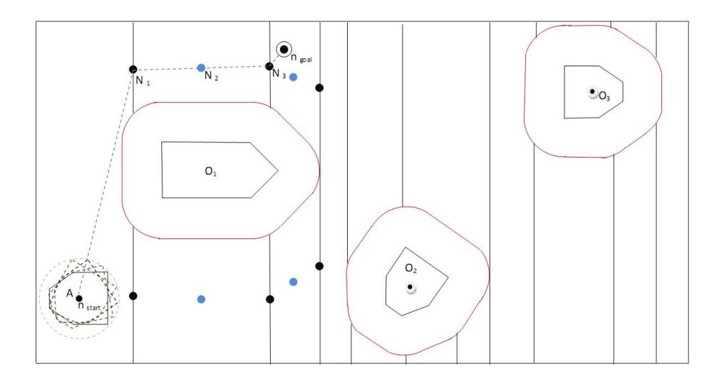
In the proposed method, the arms and feet of the standing robots and the arms, feet and the head of the other robots are observed. Then, their positions are determined and considerd as vertices of a convex polygon. Afterwards, the ball polygon is drawn and the polygons of the obstacles in the field are calculated.
In (Fig. 2), polygon O1 represents an agent laying down on the ground and polygons O2 and O3 represent standing agents. Nevertheless, as the agent is not normally able to see all of the agents' points at the same time, it can draw the largest possible polygon for them and find out the configuration-space obstacle
Walking Controller
In the initial steps we studied two type of working: static and dynamic The results of our studies are as follows:
Static walking means a stable motion in which the projection of the center of mass should be inside of a stable area in the field that cause the robot to walk slower. Dynamic walking doesn't have the limitations of static walking. In this type of walking, the agent balance depends on the whole dynamic system (speed and inertia) that cause the agent to walk faster.
We decided to use dynamic walking. Agent control in this method is divided into three parts: the first part is the control strategy, the second part is planning or other middle components. The role of these two parts is to produce reference signals for the motion of agent's joints and the third part is tracking and stabilization using different common controls. It includes controllers that were used for controling agent arms [6].
In agent walking, the first two parts are different so we discuss the relative methods into the two parts and the results are as follows:
- methods based on motion trajectory [3].
- mental methods.
- methods based on the CPG [2].
The first two methods require accurate mathematical models and the system should be defined accurately. Since achieving this accuracy is difficult and expensive (because of the simulation steps), a lot of analysis & testing is needed and each agent should be defined separately with the complete details.
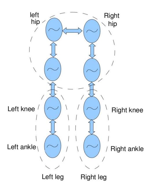
So we preferred to use the third method (CPG) that doesn't need any exact dynamic information from the agent and the environment for building a mathematical model. Neural oscillators, also known as Spinal Pattern Generators (SPG) are neural networks that can produce complex muscular activation patterns [9].
![Fig. 3. The architecture of CPG [7]](/tdps/soccer_simulation_3d__2010__Alzahra/_page_6_Figure_7.jpeg)
References
- De Berg, M., Cheong, O., Van Kreveld, M., Overmars, M.: Computational geometry: algorithms and applications. Springer-Verlag New York Inc (2008)
- Geyer, H.: A model of biped walking based on muscle reflexes that encode principles of legged mechanics. IEEE Humanoids Workshop "Modeling, Simulation and Optimization of Bipedal Walking", Zurich, Germany (2009)
- Ijspeert, A., Crespi, A.: Online trajectory generation in an amphibious snake robot using a lamprey-like central pattern generator model. In: Proceedings of the IEEE International Conference on Robotics and Automation (ICRA 2007). Citeseer (2007)
- Inada, H., Ishii, K.: Bipedal walk using a central pattern generator. In: international congress Series. vol. 1269, pp. 185–188. Elsevier (2004)
- Joseph, O.: Computational geometry in C (1998)
- Kati´c, D., Vukobratovi´c, M.: Survey of intelligent control techniques for humanoid robots. Journal of Intelligent and Robotic Systems 37(2), 117–141 (2003)
- Matsuo, T., Ishii, K.: The Motion Control of Snake-like Robot Using CPG
- Matsuoka, K.: Sustained oscillations generated by mutually inhibiting neurons with adaptation. Biological Cybernetics 52(6), 367–376 (1985)
- Minassian, K., Jilge, B., Rattay, F., Pinter, M., Binder, H., Gerstenbrand, F., Dimitrijevic, M.: Stepping-like movements in humans with complete spinal cord injury induced by epidural stimulation of the lumbar cord: electromyographic study of compound muscle action potentials. Spinal Cord 42(7), 401–416 (2004)