Dreamwing3D Soccer Simulation Team Description Paper
Zhang Qing, YangWei Min
School of Computer Science and Technology Anhui University Hefei, Anhui, China
Abstract We continue to carry on the further studied about our soccer simulation team Dreamwing3D on the base of former version. In this paper, we mainly present the structure and the techniques of our team.
Introduction
The Dreamwing RoboCup Team, starting with only the 2D soccer simulation team, was established in 2007, and then The Dreamwing RoboCup Team with 3D soccer simulation team was established in 2008. Now we have focused on Robocup 3D Simulation after three years development, we had ented the top eight in RoboCup 2010 and the top ten in RoboCup 2011.
Team Architecture
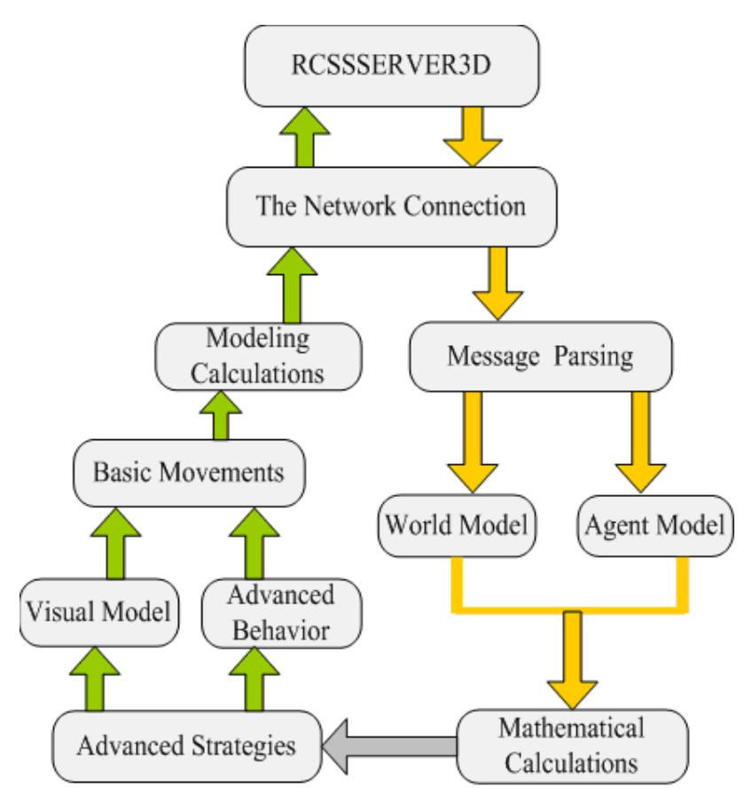
We have reconstructed architecture of our agent code and improved the reusability and scalability of it. We divide program into several functional modules: thenetwork connection, message parsing, world model, agent model, mathematical calculations, advanced strategies, advanced behaviour, visual model, basic movements, modeling calculations.
From the perspective of artificial intelligence, the most important module is high-level strategy.
From the perspective of robot, the most important module is the basic movements and modeling calculations.
High-level strategy reflects the response of the agent body under different circumstances. Basic movements mainly package a large number of the module robot's basic actions, such as stand up, play, etc.
Modeling calculation module can obtain the optimal value of walking and other movements primarily by way of kinematic model calculation.
The relationship of the various modules of the agents process has shown a clear hierarchical structure, which is shown in Figure 1.
As shown in figure 1, to obtain the joint information of characters from the SERVER through the network layer, then obtain information on the entire count message and the joint information of agent by the message parsing module, and make the high-level decision by the results of mathematical calculation. Finally, the behaviour of the Agent body be completed by the high-level decision-making to guide high-level behaviour of visual models, and calls the basic movements and modeling calculation.
Look for the Ball
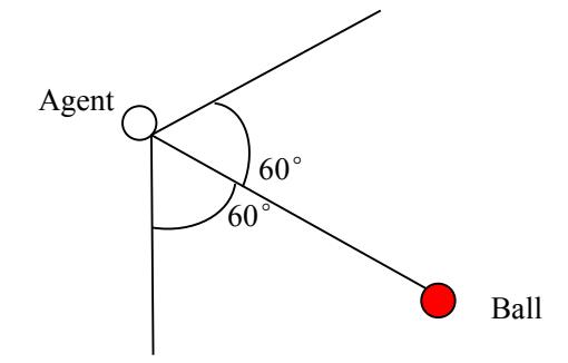
As shown in Figure 2, when the Agent is standing, it always keeps facing the ball. If the visual information can not receive the ball information in the six cycles then the ball is not within visual range, so joint rotation to the head until regaining the ball visual information. And turn the body makes the ball in the visual center.
Agent's Position
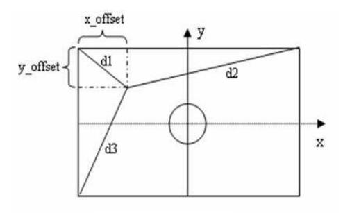
In the case of a person's height is unknown, to calculate one's position needs to see three same height of flags not on the same side at least. It means that must be able to get the three corner's flags, or three goal's flags of the polar coordinates.
As shown in Figure 3, d1, d2 and d3 are the distances of the polar coordinate. x_offset and y offset can be calculated with the cosine theorem.
$$x_{offset} = d_1 * \frac{d_1^2 + FieldLength^2 - d_2^2}{2 * d_1 * FieldLength} = \frac{d_1^2 - d_2^2}{2 * FieldLength} + FieldLength/2$$
$$y_{offset} = d_1 * \frac{d_1^2 + FieldLength^2 - d_3^2}{2 * d_1 * FieldWidth} = \frac{d_1^2 - d_3^2}{2 * FieldWidth} + FieldWidth/2$$
$$x = x_{offset} - FieldLength/2 = \frac{d_1^2 - d_2^2}{2 * FieldLength}$$
$$y = Fieldwidth/2 - y_{offset} = \frac{d_3^2 - d_1^2}{2 * FieldWidth}$$
x, y are locations of the Agent on court.
Posture
The judgment of standing and downing base on ZMP and gyroscope: It is difficult to calculate relative changes in the world coordinate system matrix ($T_{torso}^{world}$) of torse in the local visual model. So ZMP is used here to determine whether the Agent is hovering, and judge the Agent fall direction through the previous accumulated directions of gyroscope.
3-D Inverted Pendulum
The walking movements of former Dreamwing3D version are manual debugging, whose shortcomings are walking movements instability and slowly. This version uses a dynamic walking algorithm based on the three-dimensional inverted pendulum.
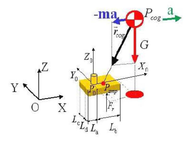
The robot simplified is shown in Figure 4: three-dimensional inverted pendulum model.
As shown in Figure 4, take ankle location as base coordinate system P0=(x0,y0,z0), so the distances of the foot ankle to the foot edge are respectively La, Lb, Lc and Ld. Thelocation of centroid COG (Center Of Gravity) is Pcog = [xcog, ycog, zcog]T and ZMP is Pzmp = [xzmp,yzmp,0]T. According to the definition of ZMP, when considering only single leg support, ZMP is at the center of the foot, so the robot's stability is the best.
After get the location of ZMP, the walking units are obtained by walking parameters and the corresponding location of COG is got by the calculation of walking unit. Then assume the relative positions of Centroid at the waist unchanged and obtain the waist position directly. Finally, calculate the track of the foot and make it to reach the desired location on time.
To get the entire leg joint angles by calculation the inverse kinematics after obtained foot and waist location.
Complete dynamic walking.
3D Gait Pattern
Traditional gait planning is generally considered two-dimensional space, which are the forward and backward. But in many cases, the Robocup 3D Simulation needs towalk in any direction, like the left post, diagonal etc. In Dreamwing3D we used 3D gait planning algorithm, which makes Agent to move in any direction without turn around, so it greatly improves the efficiency of the movement.
Multi-Agents
In the bottom, to obtain other Agent body positions through the propaganda and visual. In the high-level strategy module, to collaborate with multi-agents by the location information, which we have previously obtained.
Conclusion
To sum up, we spent a lot of time in improving the low level implementation details and high level decision making models. We also used a lot of experiments toevaluate our improvements and observed that they are efficient and useful and the results of them are good. All of features above enhance the strength of our team.
We will try to make more progress along the line that we have described in this paper.
References
- http://simspark.sourceforge.net/wiki/index.php/Users_Manual.
- Aldebaran Humanoid Robot Nao. http://www.aldebaran-robotics.com/eng/.
- Shuuji Kajita, Hirohisa Hirukawa, et al, Humanoid Robots. Tsinghua University Press. Vol.1 Mar 2007.
- Saeed B. Niku. Introduction to Robotics Analysis, Systems, Applications. Publishing House of Electronics Industry. Vol.2 Nov 2006.
- Tan Min, Xu De, et al, Advanced Robot Control. Higher Education Press. Vol.1May 2007.