ODENS 2012 Team Description
Takuya Maruyama, Hiroki Tajika, Yasuhiro Masutani
Osaka Electro-Communication University 1130-70, Kiyotaki, Shijonawate, Osaka 575-0063, Japan
https://launchpad.net/littlegreenbats/
Abstract In this paper, Team ODENS of Osaka Electro-Communication University is introduced. Especially the authors focus on methods of generating the gait and the kick motion. The gait generation is based on a three-dimensional linear inverted pendulum model,which also uses heel strike and toe off to increase the walking speed. The kick motion is planned to smoothly follow walking so that the time lag is reduced.
Introduction
Team ODENS consists of members of Masutani Laboratory in Department of Computer Science, Faculty of Information Science and Arts, Osaka Electro-Communication University, Japan. ODENS has participated in RoboCup competition since RoboCup Japan Open 2007. They participate the Small-Size Robot League, the SSL Humanoid (sub-league of the Small-size Robot League, competition of humanoid robots by using external camera), and the 3D Simulation League at present. They have participated in the 3D Simulation League since 2009. The results of ODENS in this league of Japan Open were the 4th place in 2009, the 3rd place in 2010, and the champion in 2011.
In the Department of Computer Science, students belong to professors' laboratories from the second semester of the second grade. In Masutani Laboratory, projects for RoboCup are themes for pre-seminar before regular graduation thesis. Moreover some students study RoboCup as also theme of graduation thesis.
Advantage of the ODENS simulation group is that there is a group working on real humanoid robots in the same laboratory. Although Nao isn't used, they can get hints and motivation by looking at real robots nearby.
In the following sections, the overview of ODENS is introduced in Section 2. An online gait generation based on three-dimensional linear inverted pendulum is described in Section 3. A method of generating kick motion smoothly following walking motion is explained in Section 4.
Overview of ODENS
ODENS uses libbats2.0.1 as base program, which is developed and released by the Little Green BATS. Vision and sensor signals are processed by libbats. All their efforts are focused on developing robot motion and behavior decision.
Motion of robot
Motion generating is divided into two types. One is offline and pre-described, for examples, side kicking and getting-up. The other is online and generated by the program based on the dynamics model, for example, walking and toe kicking.
The online motion generation is described in Section 3 and later.
Behavior decision
ODENS player has four roles, Attacker, Forward, Defender, and Goalkeeper. Attacker is assigned to the player closest to the ball. The other roles are assigned by their uniform number. No.1 is Goalkeeper. No.2 to No.4 are Defenders. No.5 to No.9 are Forwards.
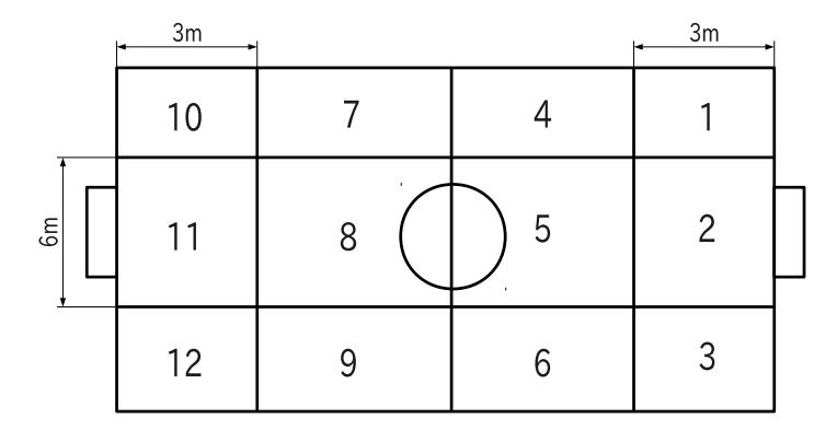
As shown in the Fig.1, the field is divided into 12 areas. Behavior of the player is determined by rule of every role based on the area where it is.
Attacker
Attacker carries the ball toward the opponent goal. It uses dribbling and kicking.
Forward
Forward stays around the ball and becomes Attacker in case that former Attacker has missed the ball.
Defender
Defender stays own team's area and interferes with the opponent in case that friend Forward has been broken.
Goal Keeper
Goalkeeper defends own team's goal while staying in front of it.
Online gait generation
In ODENS, gait is generated online. In case of offline gait generation, it is impossible to generate suitable gait for various situations. The online gait generation allows to adjust the motion to any situation.
Three-dimensional linear inverted pendulum
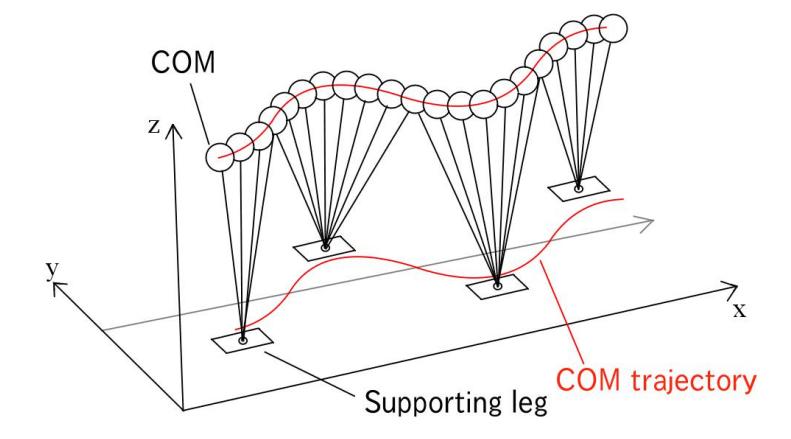
The gait generation is based on three-dimensional linear inverted pendulum model. This model consists of a mass point and an expandable massless rod. The mass point corresponds to the center of mass(COM) where the whole mass of the robot is concentrated. the rod corresponds to the supporting leg and contacts the floor at its tip. While the right and left legs support the mass point by turn, the pendulum model connects to the next model as shown in Fig.2. In order to generate the gait, first the trajectory of COM is computed. Second angles of all joints in supporting leg are obtained by solving inverse kinematics of the COM. Finally, the position of foot of swing leg is determined, then the angles of all joints in swing leg are obtained. Angular velocity command of each joint sent to the server is computed from the trajectory of its angle.
Heel strike and toe off
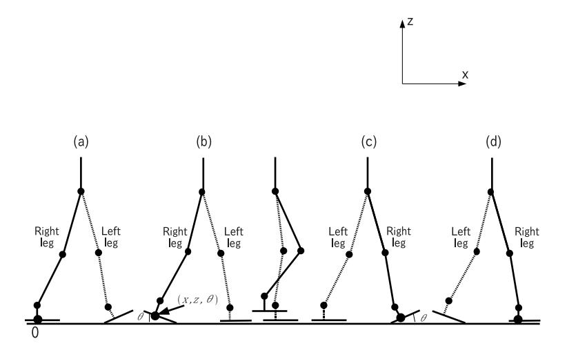
The inverse kinematics of the legs becomes easier by adding the condition that the foot is kept horizontal. However, under strict limit of joint angular velocity, the limit prevents the leg from moving faster. To overcome this problem, heel strike and toe off[3] are introduced to the gait generation. The heel strike means that the swing leg makes contact with the floor at heel first. The toe off means that the swing leg makes a takeoff at toe last. Fig.3 shows walking patterns with heel strike and toe off.
Swing leg trajectory
The motion of swing leg is designed in joint angle space, because the limit of joint velocity is strict.
Variety of walking
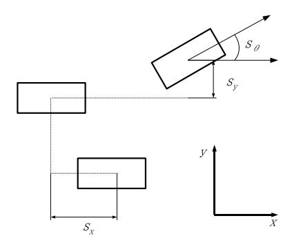
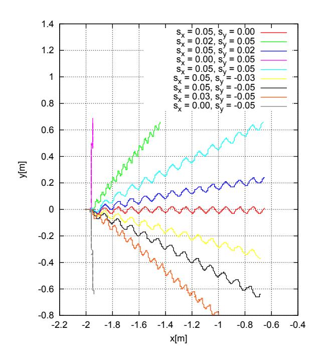
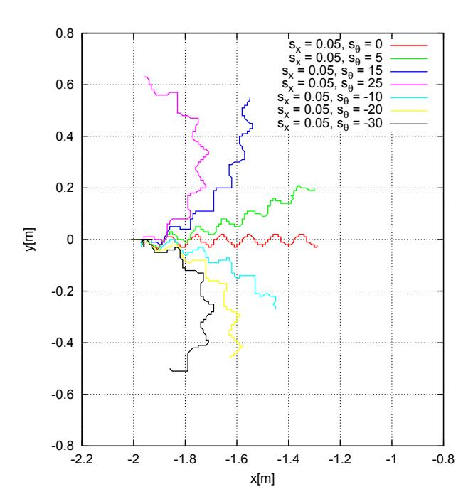
The gait is determined by four parameters, the period, the stride in forward direction $s_x$, the stride in side direction $s_y$, and the turning angle $s^\theta$ as shown in Fig.4. To confirm variety of gait, trajectories of the torso position in the horizontal plane for several parameters in case of parallel walk and turning walk are shown in Fig.5 and Fig.6 respectively.
Generation of kick motion following walk
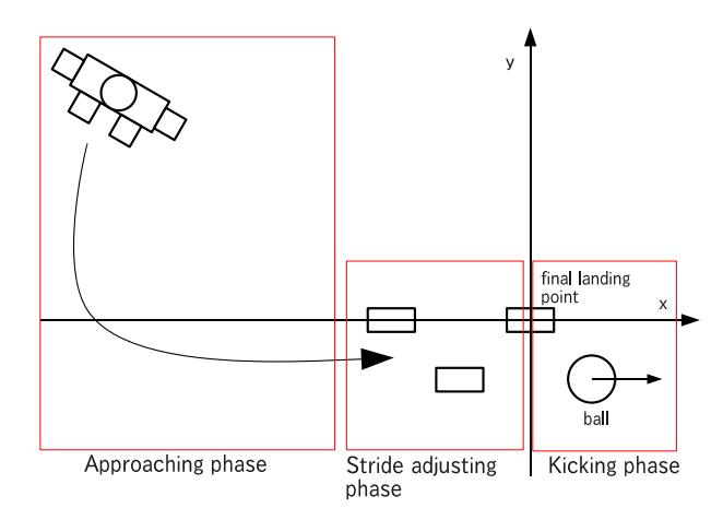
In the program of ODENS 2011, since walk and kick are separated, it takes extra time to kick the ball after walking. To reduce the extra time, kick motion continuously following walk is developed. In the program of ODENS 2012, kick following walk consists of three phases, "approaching phase", "stride adjusting phase", and "kicking phase". In the approaching phase, the robot walks to the proper point in the rear of the ball. In the stride adjusting phase, the robot adjusts its stride so that the last stride is maximum and landing point of the supporting leg is appropriate just before kick. In the kicking phase, the robot brings its toe close to the ball and hits the ball at maximum speed. In this explanation, positions and directions are represented in the coordinate system whose origin corresponds the final landing point before kick, whose x-axis corresponds to the direction of kick and, whose z-direction corresponds to vertical upward as shown in Fig.7. The maximum stride in the forward direction is denoted by $x_{max}$ hereafter.
Approaching phase
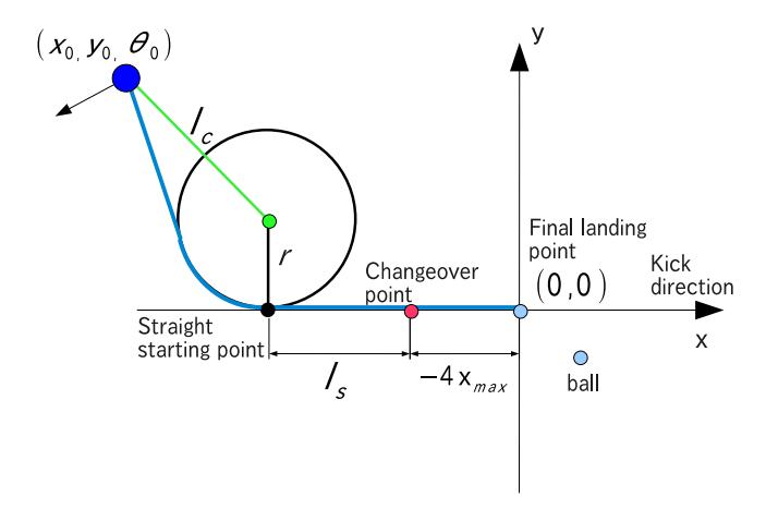
In the approaching phase, the planned path is constructed from three types of walk, straight walk, curved walk, and pivot turn. "straight starting point" and "changeover point" are defined as shown in Fig.8. At the straight starting point the robot starts walking straight in the direction parallel to the kicking direction. At the changeover point, it switches over the stride adjusting phase. The purpose of the section between the two points is to get enough speed and to reduce the direction error. The path can be determined as follows;
- In case that the initial point is outside of the circle with minimum turning radius, pivot turn → straight walk → pivot turn
- In case that the initial point is inside of the circle with minimum turning radius, pivot turn → straight walk → curved walk
Stride adjusting phase
The changeover points is denoted by $(-x^l, 0)$, where it is assumed that $3x_{max} < x^l < 4x_{max}$ and there is no direction error. Let the last stride before kick equal the maximum stride $x_{max}$. As a result of that, the rest distance $x^l - x_{max}$ is over 2 steps and 3 steps or less of the maximum stride. For example, if the pivot leg when kicking is left, the number of steps to walk for $x^l - x_{max}$ is 3 in case that the starting leg in this phase is left, otherwise 4. The stride $s^x$ is determined by Eq.(1).
$$s_x = \begin{cases} \frac{x_l - x_{max}}{3} \text{ (the starting leg is same side as the pivot leg)} \ \frac{x_l - x_{max}}{4} \text{ (the starting leg is different side from the pivot leg)} \end{cases}$$
Kicking phase
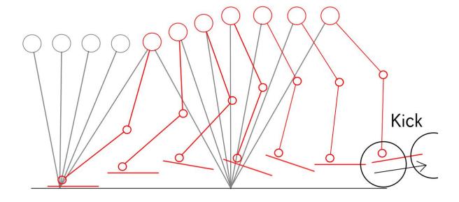
In the kicking phase, the supporting leg at the final landing point becomes a pivot leg. The swing leg becomes a kicking leg. The motion of kicking leg is planned so that the horizontal velocity is maximized when it contacts the ball. The motion of pivot leg is solved from the COM motion base on the linear inverted pendulum model in the same way as the gait generation. In addition COM is lifted up in order to stretch the kicking leg so that its toe velocity is as high as possible. Fig.9 shows the stick diagram in the kicking phase.
Experiments for evaluation
In order to evaluate the effectiveness the proposed method, results of ODENS 2011 and 2012 are compared as shown in Fig.10 and Fig.11 respectively. They are the trajectories of torso and footprints from the initial point $(-2, 1)$. It is found that the conventional method (ODENS 2011) wastes time in front of the ball. On the other hand, the proposed method (ODENS 2012) can kick the ball after walking without stop.
Another result of comparative experiment is shown in Table 1. They are averages and standard deviations of the required time and the distance of carry for ten trials in case that the initial point is $(-4, 0)$ and the ball is placed at $(0, 0)$. The required time of the conventional method is about 5[s] shorter than the conventional method. There is no difference of the distance of carry between the two methods. In addition, while the result of the conventional method has dispersion, the result of the proposed method is uniform.
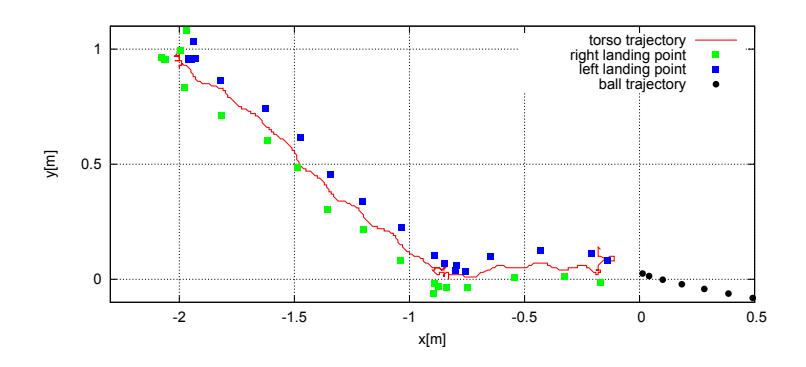
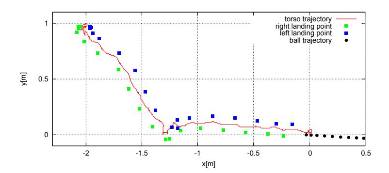
Table 1. Comparison between proposed method and the conventional method
| The conventional method (ODENS 2011) | The proposed method (ODENS 2012) | ||
|---|---|---|---|
| Time required | Average | 16.10[s] | 11.20[s] |
| Standard deviation | 2.88[s] | 0.00[s] | |
| Distance of carry | Average | 3.12[m] | 3.11[m] |
| Standard deviation | 0.43[m] | 0.11[m] |
Conclusion
In this paper, the authors focus on the gait generation based on three-dimensional linear inverted pendulum model and the kick motion following walk. The various walk and the kick after walk without stop can be realized. In the future, the authors will study and develop stabilization of walk by sensor feedback control and cooperation (teamwork) of multiple robots.
References
- Little Green BATS ,https://launchpad.net/littlegreenbats/.
- Shuuji Kajita,Humanoid Robot,Ohmsha,2005 (in Japanese).
- Masamichi Ozeki, Chi Zhu, Atuo Kawamura, "High Speed Walking of Biped Robot by Walking Trajectory Modification with ZMP Control", The Papers of Technical Meetingon industrial Instrumentation and Control, IEE Japan,pp75-80(2007).