Paydar 3D Soccer Simulation Team Description
Mohammad Razeghi
Sharif University Of Technology
Abstract Soccer simulation is an effort to research in fields of Artificial Intelligence and Robotics. Therefore our team has based its strategy on Artificial Intelligence principles. This paper simply describes the approach chosen by Paydar soccer simulation 3D team including connection with server, analyzing messages, high level and low level skills implemented by our team.
Introduction
Soccer simulation is a multi-agent environment in which the communication between client and server is conducted. It enables us to conduct experiments and tests on the simulated object regardless of the hardships one may face conducting the same experiment is a physical environment. In 3D soccer simulation competitions two teams consisting of humanoid robots challenge one another's skills. Each team will receive information from the server. Afterwards the client sends instructions to the server and this procedure will occur until the end of the game.
2 Technical Description Report
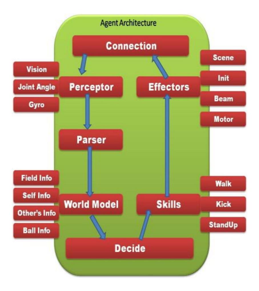
General architecture of our team is shown in figure 1. Connection with server is handled by class Connection. This class is able send and receive information to and from the server. Messages received from server are analyzed in Parser and then the analyzed data will be stored in class WordlModel and then the process of positioning will commence. High level and low level procedures are available through class Skills.
2.2 Skills
The word skills refers to action a robot may take such as walking, shooting, turning.Some of these will be explained in the following.
2.2.1 Walking
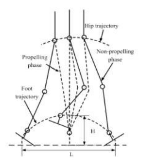
By observing the human race and closely examining the action of walking we came to understand the parts that play significant roles in this process.
The results of our experiment is as follows:
- I. The trajectory of the ankle is approximately an oval-shaped route around the supporting leg.
- II. The trajectory of the hip is also an oval-shaped route.
- III. For reasons of simplification we've assumed that the surface of the foot is parallel to the surface of the ground.
For implementation there were also some considerations as follows:
- I. We have ignored forces during motion.
- II. We estimated the weight and the fraction between the foot of the robot and the ground so that the robot does not slip with one foot on the ground.
With the earlier mentioned in mind and the aid of inverse kinematic we've designed this algorithm:
I. The destination of each of the three parts(The ankle of the free leg, The hip of the supporting leg and the hip of the free leg ) will be calculated.
- II. These coordinations will be sent to the inverse kinematic :
- (a) An equation will be formed beginning at the ankle of the supporting leg and finishing at the point where the hip of the free leg is located. Therefore effective angles will be calculated.
- (b) The position of the hip of the free leg determines the direction of the waist of the robot and for this cause the angles calculated at section 2.1 will be used and the relative direction of the waist (relative to the hip of the supporting leg) will be calculated and the angle of the joint in action will be calculated.
- (c) All the angles we calculated in aforementioned parts will affect the forward kinematic and the position of the ankle of the free leg will be calculated relatively to the hip of the free leg and then the angle of the joint in action will be calculated.
- III. Error and Error Removal . If the positioning is so that there are no results from the inverse kinematic and if the generation of motion route is flawed the calculated angles will be invalid and not taken into account.
- If the loss of results occurs due to confinement of angles the latter mentioned angle will reach its maximum and a new set of angles will be stored as the answer.
- IV. Feedback . If for any reason the robot is unable to act according to the angles it receives, there will be no new locations generated for each part and alternatively the equation will be solved using the former locations.
2.2.2 Shooting
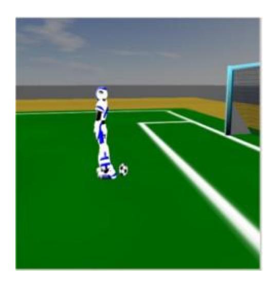
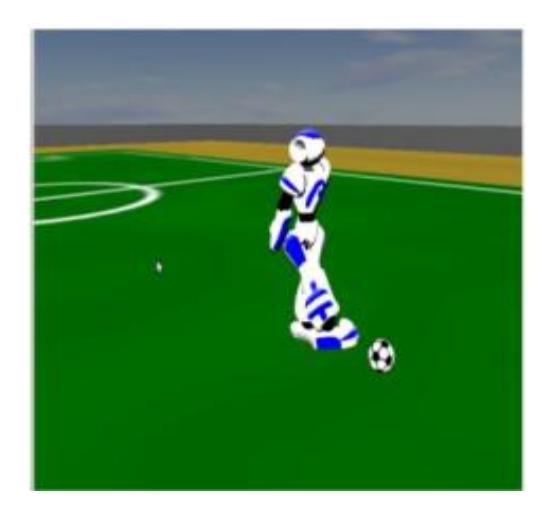
In order the perform the action of shooting and estimating the location of the target our team has decided to use a Trainer programmed by the members of our team. For this purpose the robot and the ball will be placed in different situations and locations in the field and different shots taken will be tested and by storing all the data received from this experiment the optimum result will be stored in a file and will be used in the game.
3 Conclusion and Future Work
What you read was a description of our team and we are currently working on the improvement of basic moves such as shooting and walking and positioning. Aside from that we intend to add abilities such as decision making algorithms to our code.
References
- Qiang Huang, Kazuhito Yokoi, Shuuji Kajita, Kenji Kaneko, Hirohiko Arai , Noriho Koyachi and Kazuo Tanie , Planning Walking Patterns for a Biped Robot
- Xu Yuan , Tan Yingzi. "SEU-3D 2007 Soccer Simulation Team Description"
- M. Tim Jones. "AI Application Programming"
- www.SourceForge.net/projects/simspark. "Simspark Manual"
- Stuart Russell , Peter Norvig. "Artificial Intelligence: A Modern Approach"
- Robin R. Murphy٫ "An Introduction to AI Robotics"
- Hosein Ansari, Armin Ildermi, Sina MolaviPoor, Mohammad Jafar Shokri ,Mahdi Aledaghi. "Nexus3D Soccer Simulation Team Team Description"